richardm6994
|
| posted on 31/12/12 at 11:28 AM |

|
|
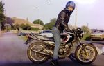
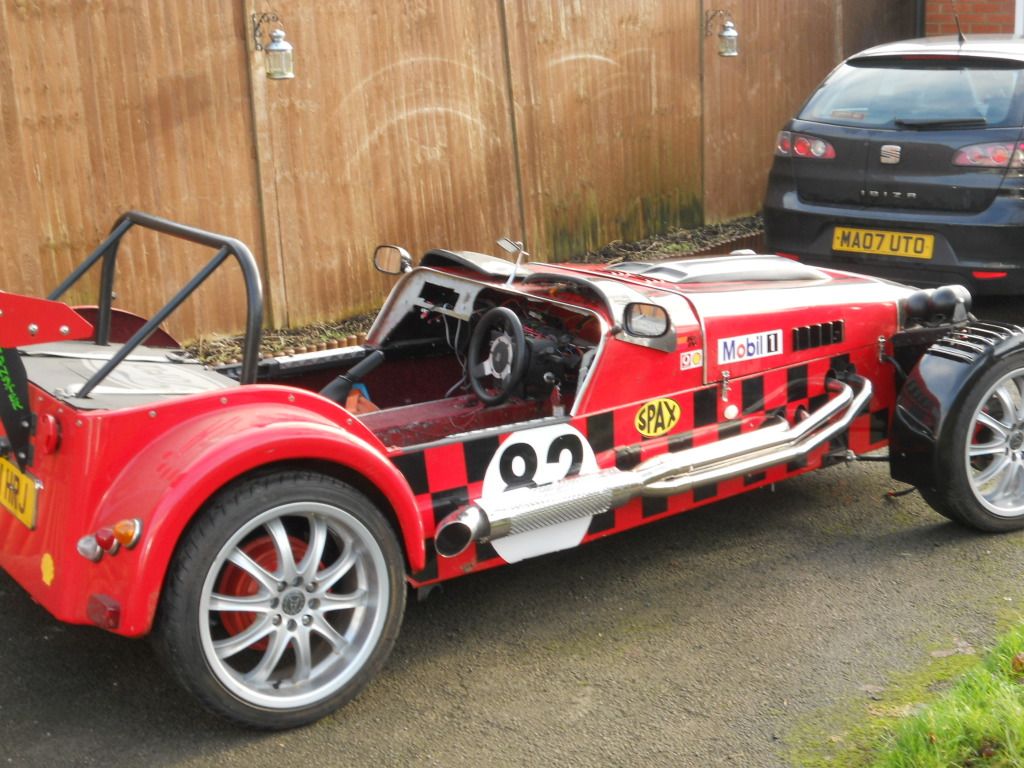
rover v8 onto type 9 & into robin hood exmo
Hi folks, I've decided to write up my V8 project on here. Please excuse the photo sizes!
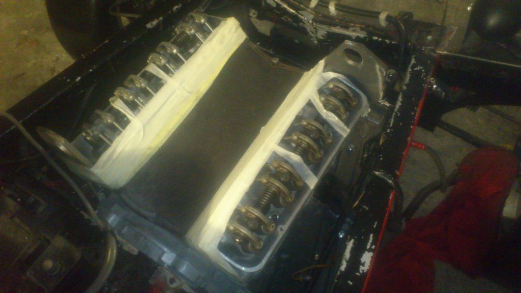
So starting at the begining, I bought this engine from a friend who spend all summer lovingly rebuilding it, only to have to sell it before he got
chance to fit it in his car due to some unforeseen circumstances. I would never take credit for someone else's hard work, he's done a
fantastic job and here are a few photos from his engine build;


Okay, so this is the bit where I take over....
The project specification so far is as follows;
3.9 serpentine V8 (re-built)
Piper 285 cam
9.75:1 CR
Duplex Timing Chain
1.6:1 rockers
Stage 3 heads
JWR Offenhauser Duel Plane inlet manifold
Edelbrock 500 carb
Megajolt ignition
Facet red top fuel pump
Superlight flywheel
AP Racing Clutch
Type 9 gearbox connected to engine via adapter plate and SD1 Auto Bellhouse. The type 9 im using is uprated by a company called first-motion who have
spec'd the gearbox to 260bhp (and I can't remeber the torque figure but we worked out that the box will more than cope).
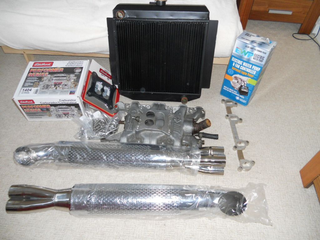
4-core radiator
115 l/s electric water pump (ally housing) with digital controller (for vary pump and fan speeds).
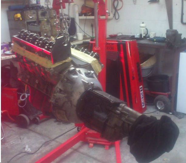
Photo below is the bit's I've got so far (I've also got the clutch and flywheel but they are in the garage);
I see this project breaking down into 4 main sections;
1) Engine onto gearbox
2) Engine into car (new mounts etc...)
3) Exhuasts
4) everything else
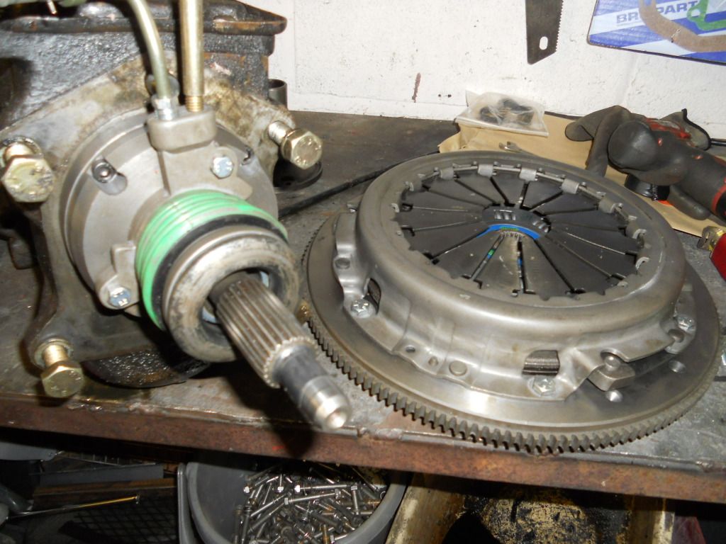
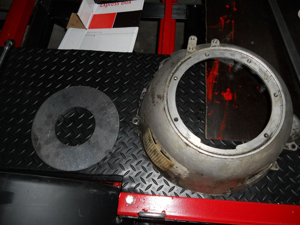
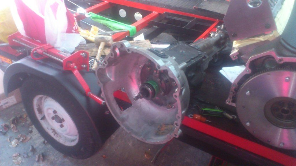
Section 1 - Engine onto gearbox
For this solution, basically bolt the SD1 Automatica bellhouse onto an "polo mint" shape adapter plate (15mm thick) and then this bolts
onto the gearbox.
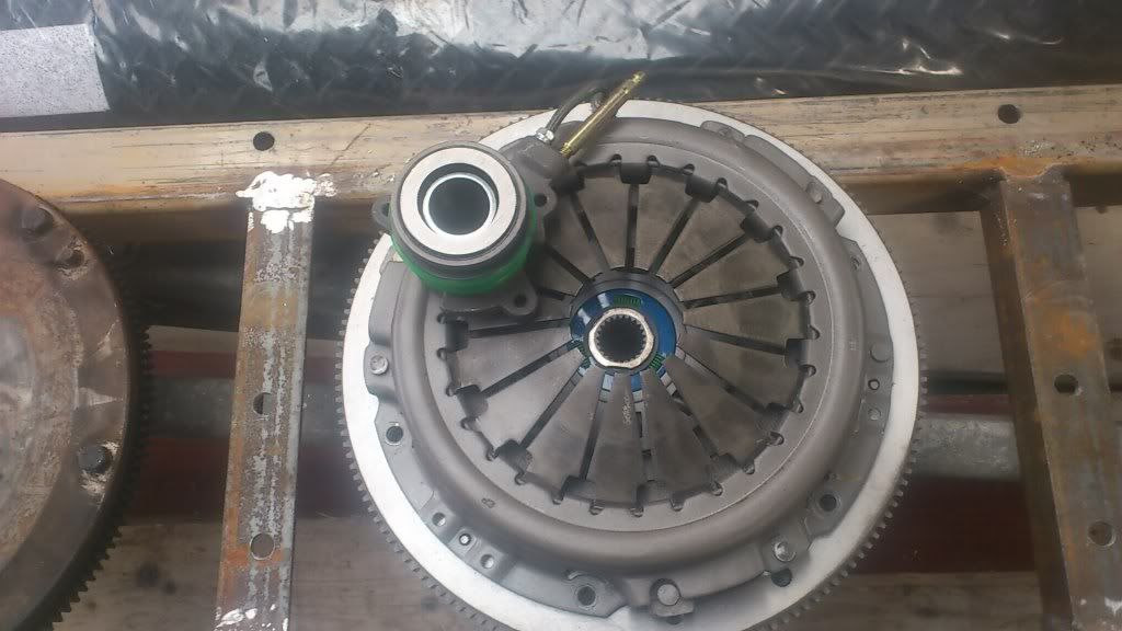
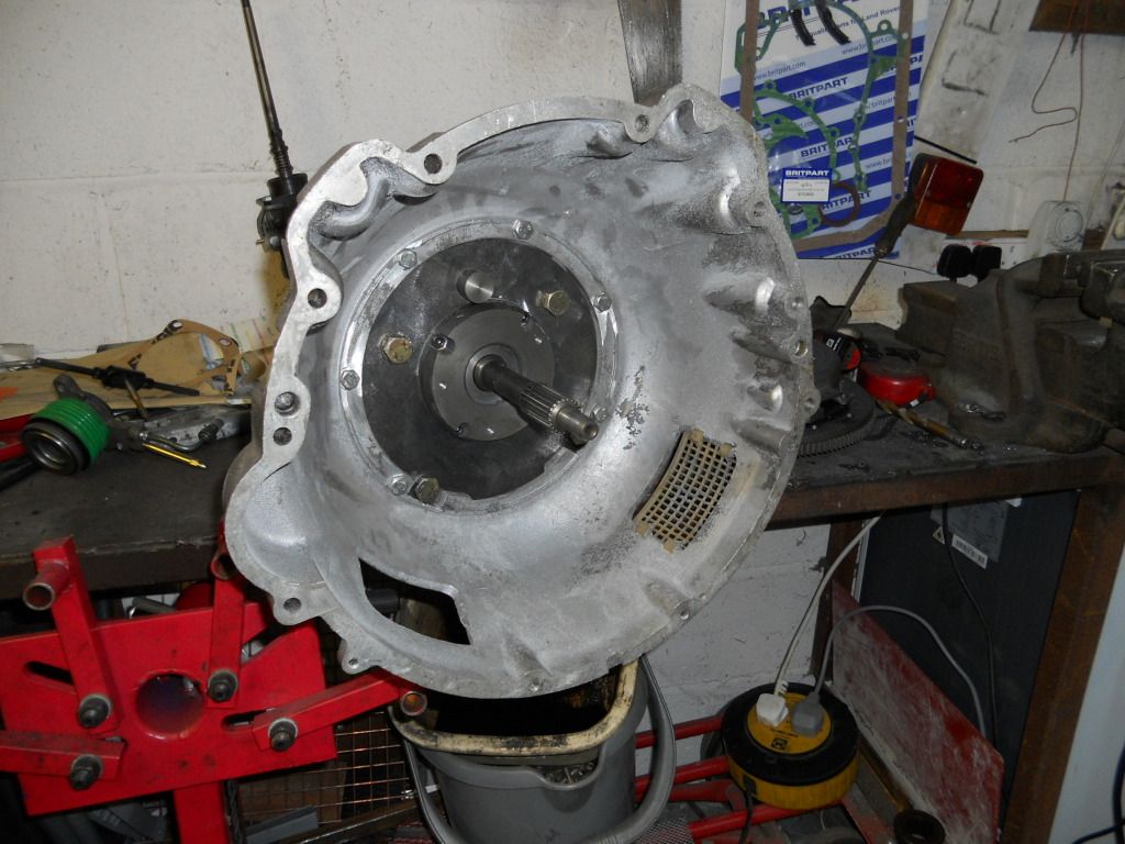
The Rover SD1 clutch has the same spline as the ford type 9 gearbox so this is quite handy
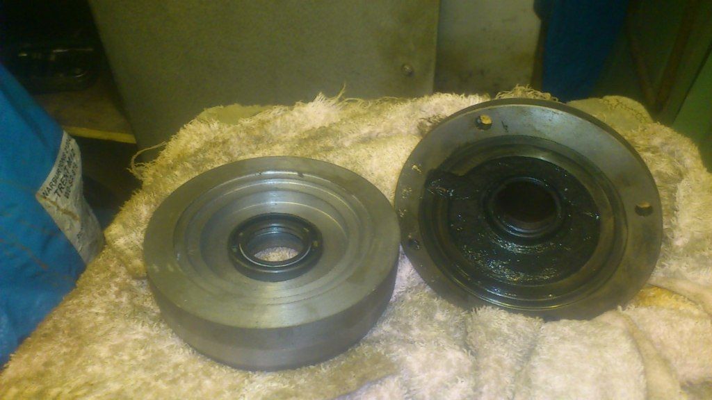
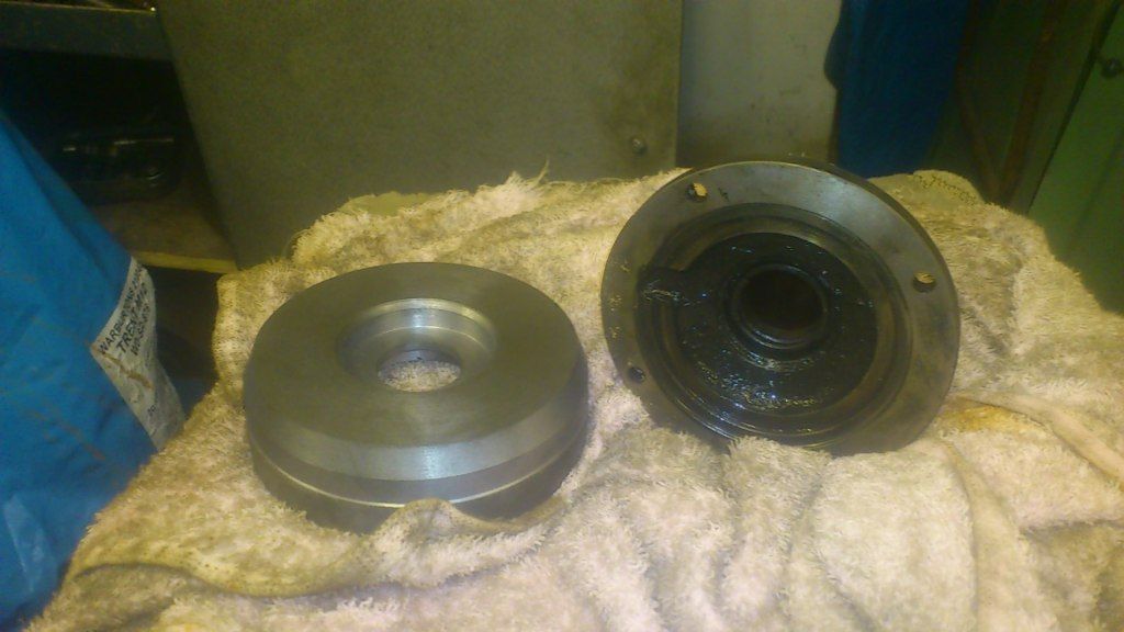
You also have to use the ford galaxy slave clutch cylinder. This cause me a slight problem being that the hole formed by the ends of the clutch
pressure plate fingers is 1mm smaller than the diameter of the hydraulic clutch and release bearing assembly (ford galaxy) which I am using. As such,
each clutch finger only sits on the release bearing face by 0.5mm which I did'nt feel too comfortable about.
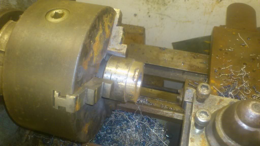
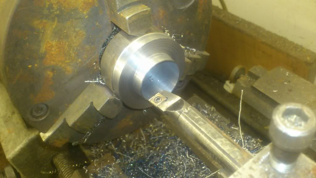
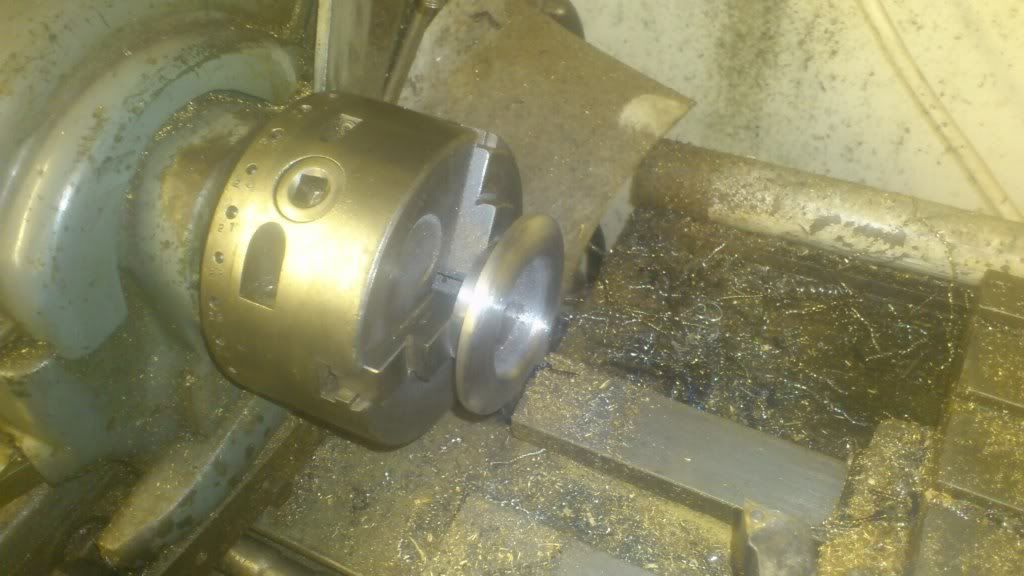
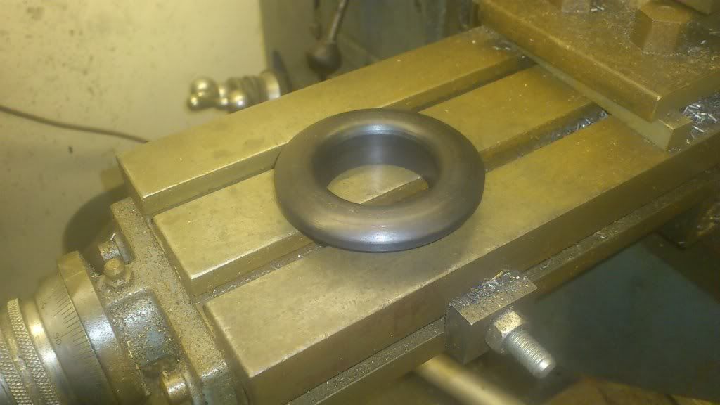
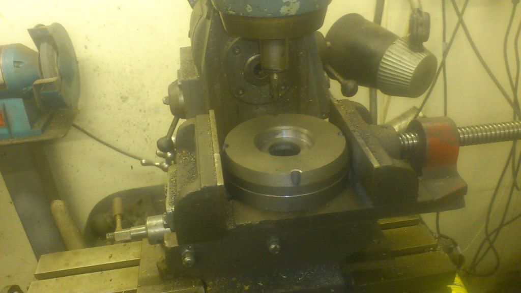
so my solution has been to turn a new bigger face for the release bearing out of some EN8 steel (case hardened after machining) to sit over the ford
galaxy release bearing face (1 thou interferance "tight" push fit). I've curved the new face to match the rover release bearing
which came with the clutch;
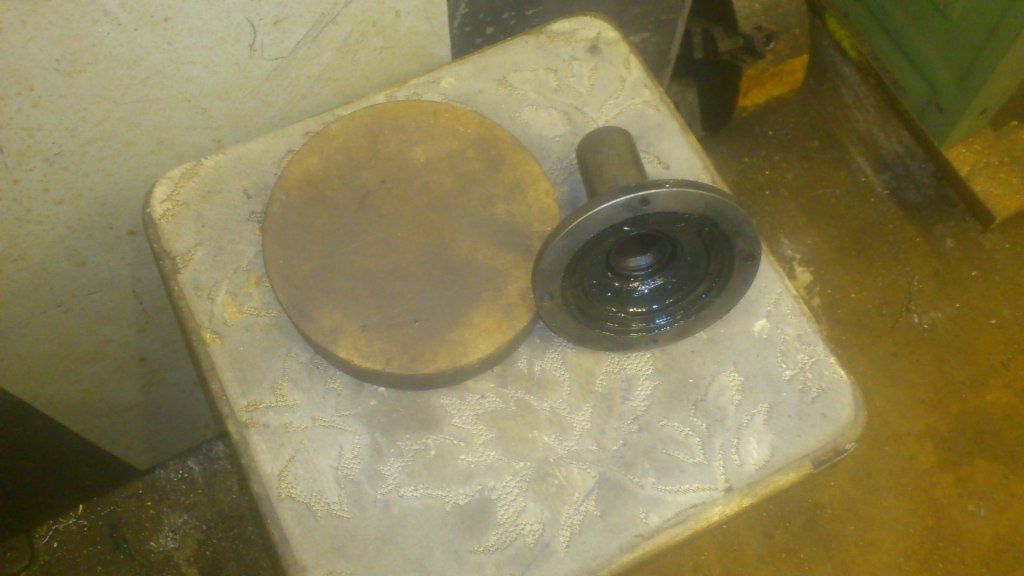
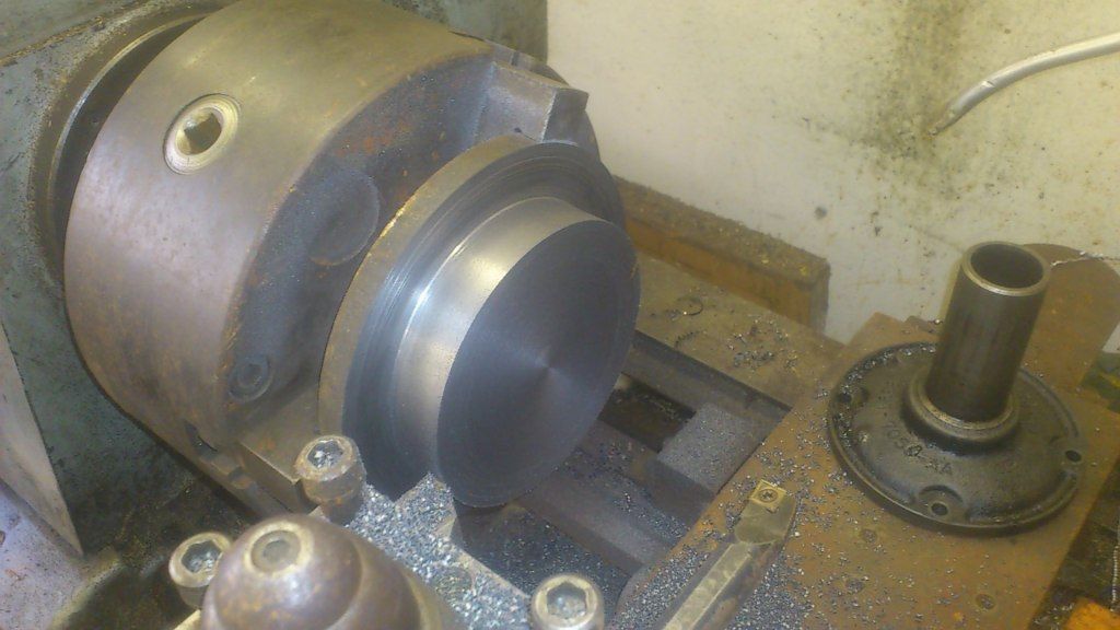
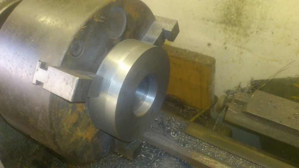
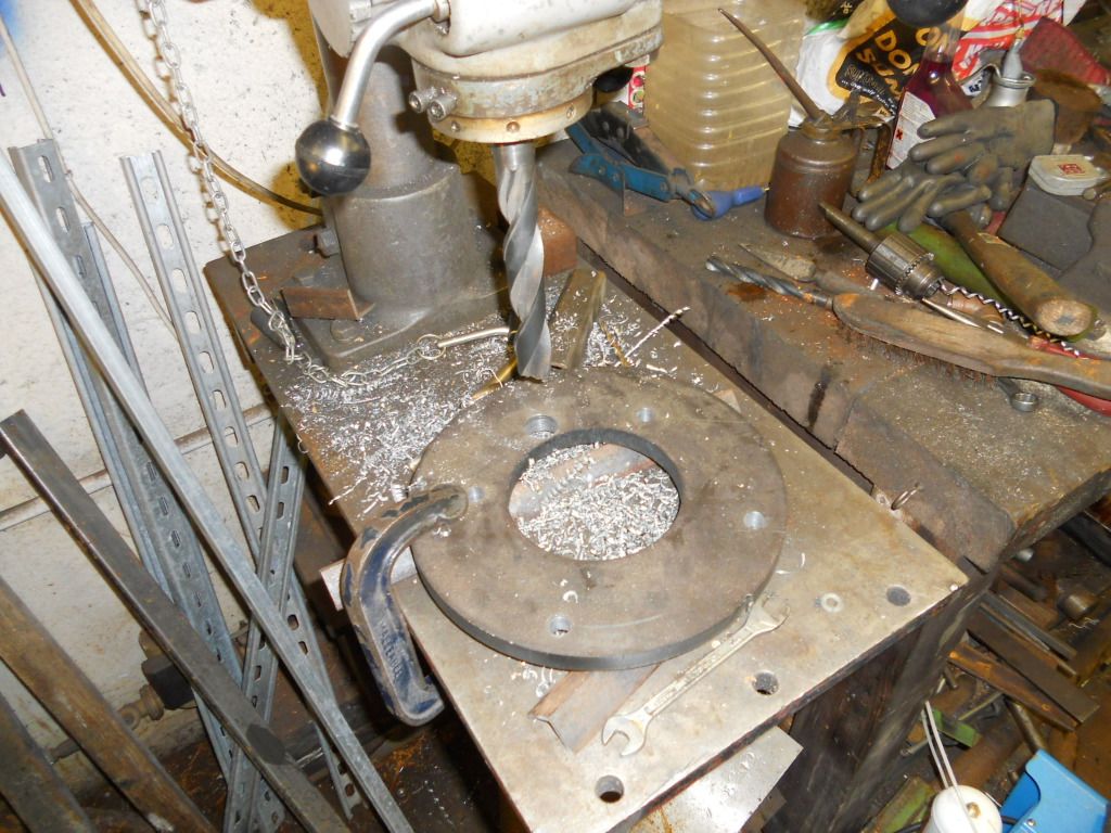
Next I've had to replace the input shaft cover from the type 9 and make a replacement cover which also holds the hydraulic clutch (the correct
distance away from the gearbox face to ensure enough clutch travel to disengage) and then make a polo mint 15mm thick steel adaptor plate;
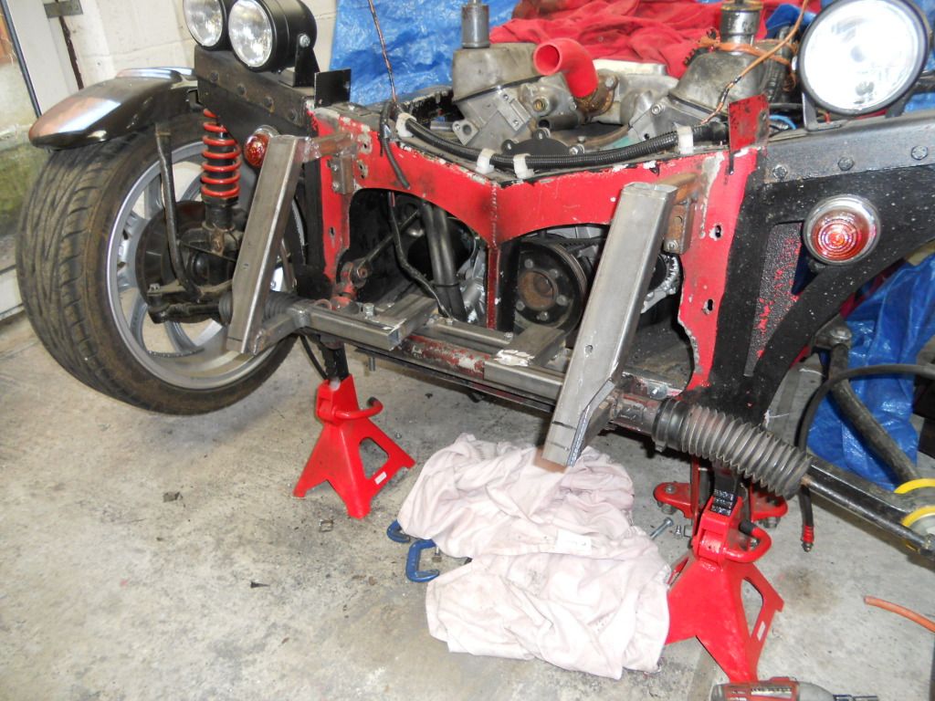
Section 2 - Engine Mounts;
Firstly I'm going to start off by saying that I know that this solution is probably overkill...but I'd rather overkill it than underkill
it and end up twisting the chassis etc...under the torque of the v8.
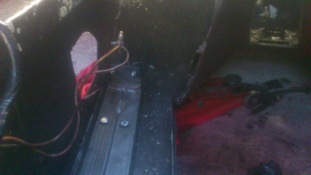
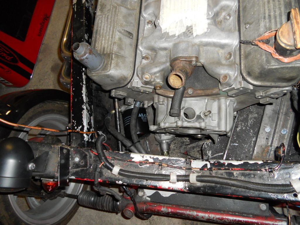
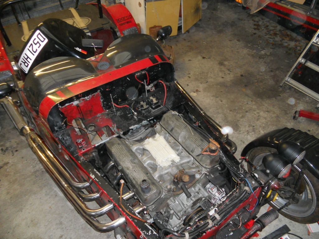
1) This is how the engine bay looks with the original exmo mounts for the pinto engine.
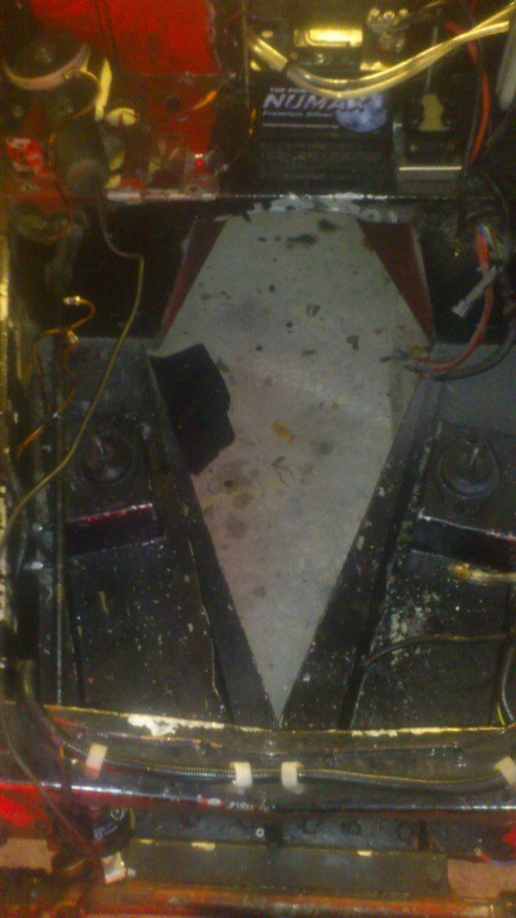
2) The first job is to cut these original mounts out with Mr. angry-grinder. I also had cut away some of the floor away for sump clearence.
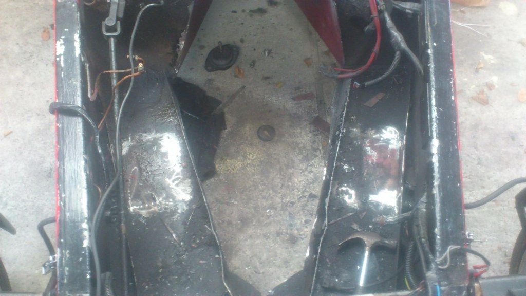
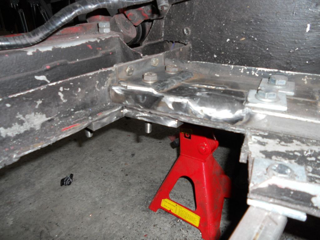
3) Next I ran 4 peices of 3mm wall box section (2 per side) down the length of the engine bay and bolted them to the floor. For the sake of this diary
I'm calling these "engine-rails" I welded the two peices of box together for added strength. NOTE: some nice square washers will be
making there way from my dads workshop to use either side of each bolt!
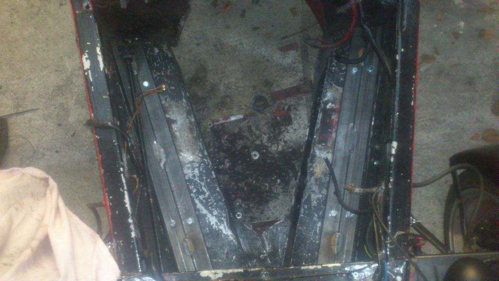
4) Then I cut out my engine mount brackets from some nice thick bright mild. To get these in the right location, I bolted them onto the engine,
dropped the engine back into the engine bay, got everything level & centred and then tack welded the brackets onto the engine-rails
5) I whipped the engine back out, and fully welded the brackets onto the rails and added some angles at the ends of the rails for additional
strength
6) and there we have it...engine in back in and all bolted up to the back wheels
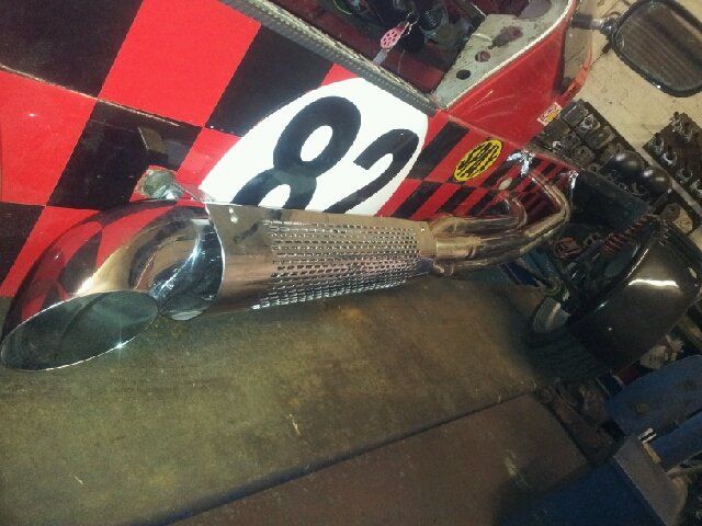
Section 3 - Exhausts
As photos above, I've got the side pipes, 4-1 merge collectors and exhaust flanges. I've thought long and hard about doing the header
pipes myself.....however I've decided to leave it with someone with far more experience than me, especially given that the exhaust system is a
key visual feature of the car! I don't want it looking rubbish!
The car goes in Jan to have these fabricated so what this space.......
|
|
|
|
|
richardm6994
|
| posted on 3/1/13 at 05:17 PM |
|
|
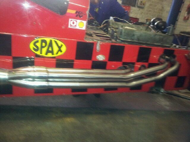
Exhausts are booked with PD Gough Nottingham.
Dropping the car off on Tueday the 8th and collecting on Friday 11th.
I'm supplying the side pipes, 4-1 merge collectors and exhaust flanges and they are mounting the side pipes and fabricating the headers.
£400 per side in polished stainless so £800 in all. I've seen his work on other 7's and it is really good!
Looking forward to seeing the results, however the "engine-fund" will be somewhat lighter!!
|
|
|
coozer
|
| posted on 3/1/13 at 05:56 PM |
|
|
Good work, I need some exhausts for my V8 but there's no fund big enough here to pay what your paying
Any pics of any nice steam engines?
1972 V8 Jago
1980 Z750
|
|
|
richardm6994
|
| posted on 3/1/13 at 07:26 PM |
|
|
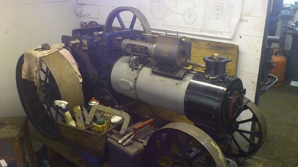
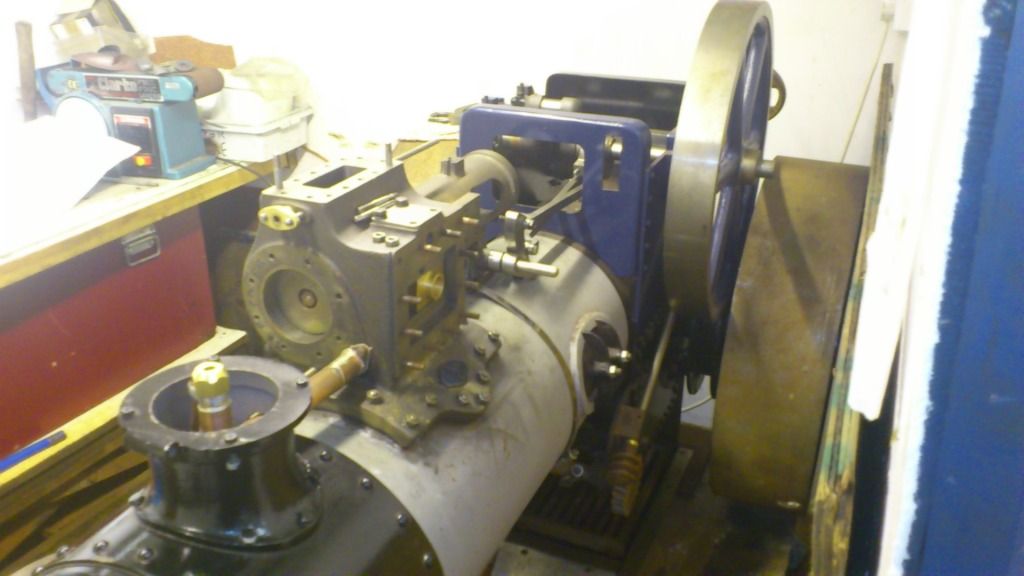
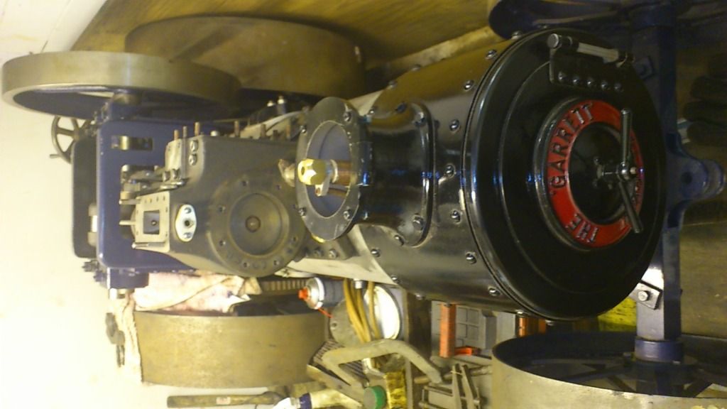
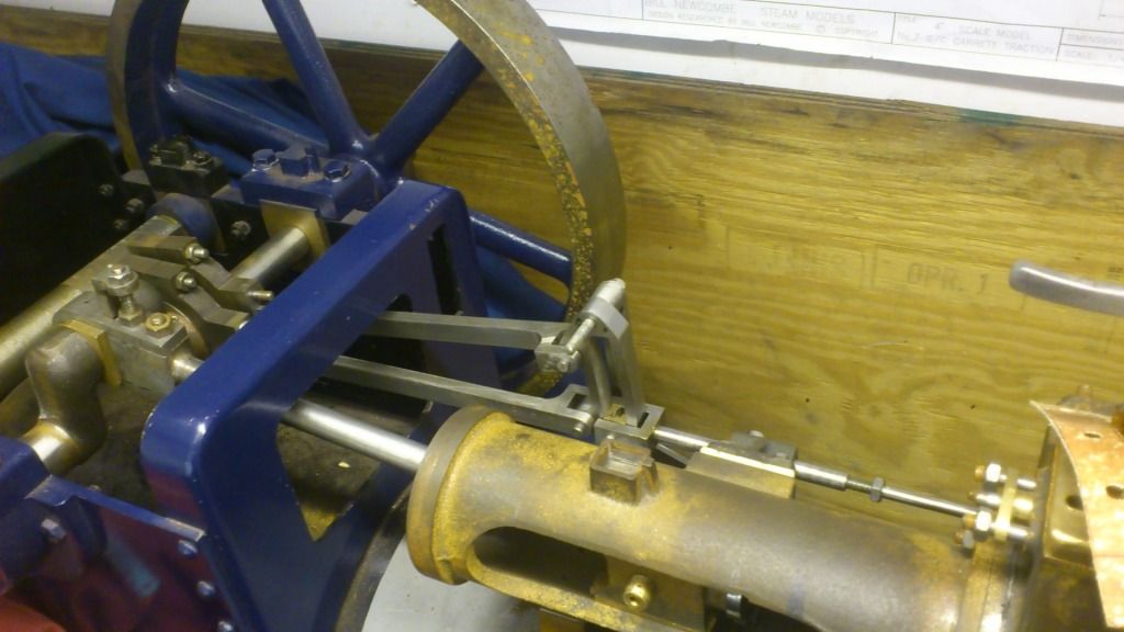
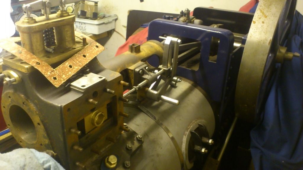
go on then. This is a 1/3 scale garrett traction engine I've been building for more years than I care to remember!
The casting come in raw state and all the machining is done at home. Everything else is scratch build.
|
|
|
richardm6994
|
| posted on 3/1/13 at 07:32 PM |
|
|
And this is a video I came across on tinterweb. It's my 5 inch gauge Midland Compound loco (driven by my dad in the video). Once again, scratch
build from raw castings.
http://www.youtube.com/watch?v=cj4cO1JG__8
|
|
|
richardm6994
|
| posted on 9/1/13 at 05:43 PM |
|
|
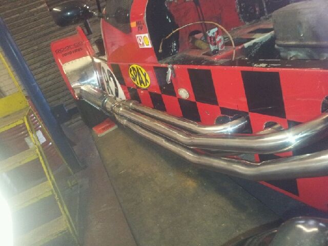
PD Gough have just txt me some photo's. Not the best quality pictures because they've been txt'd but you get the idea!
|
|
|
coozer
|
| posted on 9/1/13 at 05:47 PM |
|
|
quote:
Originally posted by richardm6994
And this is a video I came across on tinterweb. It's my 5 inch gauge Midland Compound loco (driven by my dad in the video). Once again, scratch
build from raw castings.
http://www.youtube.com/watch?v=cj4cO1JG__8
Excellent indeed
1972 V8 Jago
1980 Z750
|
|
|
richardm6994
|
| posted on 11/1/13 at 05:06 PM |
|
|
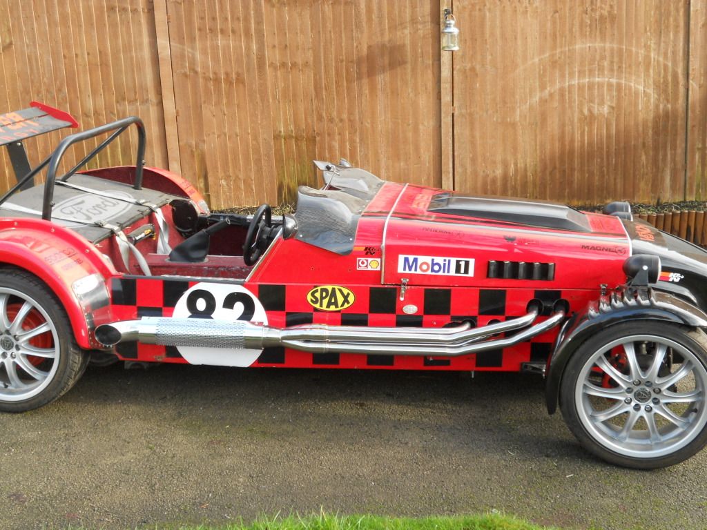
Got the car home this morning & it looks even better in the flesh than the picture-txt I got the other day!
PD Gough have made me some trims to go around the body work holes but havn't fitted them because I told them the engine is coming back out again
before the project is complete.
I started this diary splitting the project into 4 sections;
1) engine onto gearbox - DONE
2) engine into car- DONE
3) exhaust - DONE
4) everything else
Okay, now I'm on the last section, I'm going to break it down even further;
4a) finish engine rebuild
4b) fuel system
4c) remote oil filter (due to clearence issues)
4d) alternator and starter
4e) megajolt stuff
4f) Carb with throttle cable bracket, tps bracket
4g) electric water pump and radiator
4h) pedal box with hydraulic clutch
So still a long way to go, but a lot of the above are just "bolt-on" bits so at the moment there seems to be a mountain to climb, but
I'm sure I'll be ticking-off the jobs pretty quickly.
In the mean time, I'm going to spend today looking at the car and imagining that it runs!!!
|
|
|
richardm6994
|
| posted on 20/1/13 at 10:40 PM |
|
|
Time for a bit of an update...not much of one though because of the 72hr weeks I'm having to do at work this month....without overime or
time-in-lue ...anyway, before I get into a rant about work...
I've decided that I only want to take the engine out one more time before final fitment. As such, I'm going to position all the bits and
bobs in the engine bay so that when I take the engine out for the last time (hopefully), they can all be easily access for a final fettle / finish
off.
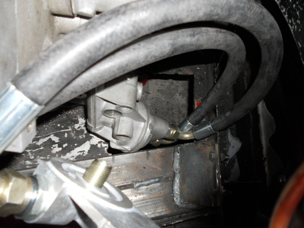
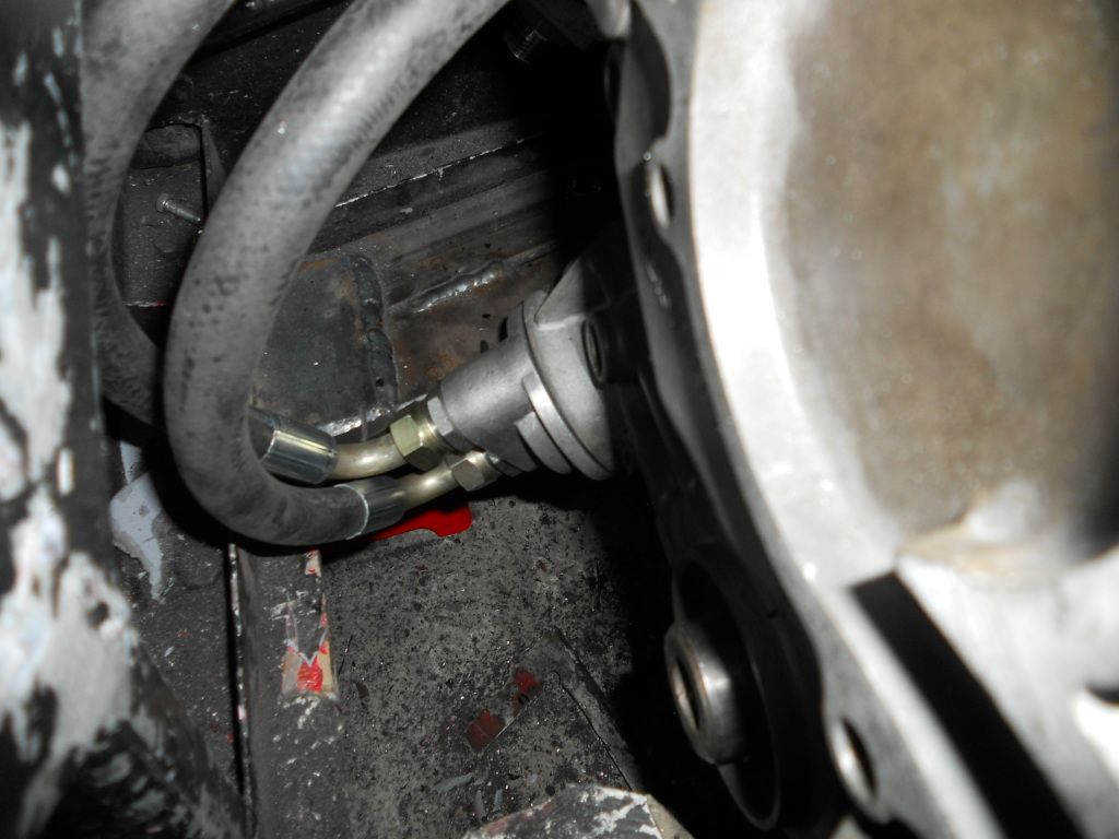
So the first bit I've started with is my remote oil filter. I thought this would be straight forward...yeah right!!
The first thing I tried was a sandwich plate I had laying around from an old oil radiator. The problem was that it was too big in diameter and stuck
out too far.
So next I got myself a different oil take off plate. This fits nicely but the angle which it points downwads has meant the removal of yet more of the
engine bay floor! I wasn't too keen on doing this but could see no other choice so out came Mr Angry grinder.
I plan on adding some cross bracing to add some strengths back to the width of the engine bay and trimming back the engine box-section rails (to give
more clearence to the take off plate) once the engine has been removed.
|
|
|
richardm6994
|
| posted on 25/1/13 at 12:36 AM |
|
|
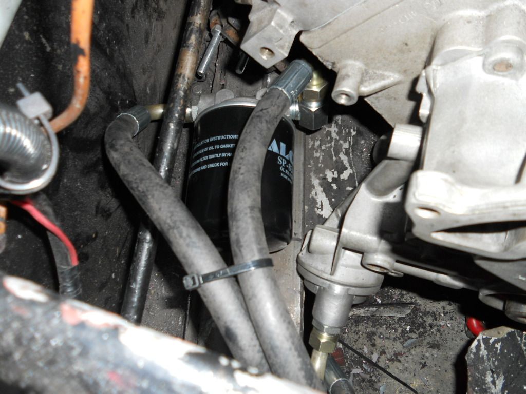
just a quick update to finish off the remote oil filter....(next job alternator bracket)
3 things I'm looking forward to most;
Seeing the engine & engine bay all painted up looking nice.
Hearing the exhausts.
The feel of the extra 100bhp over my old pinto!!!
|
|
|
richardm6994
|
| posted on 27/1/13 at 05:05 PM |
|
|
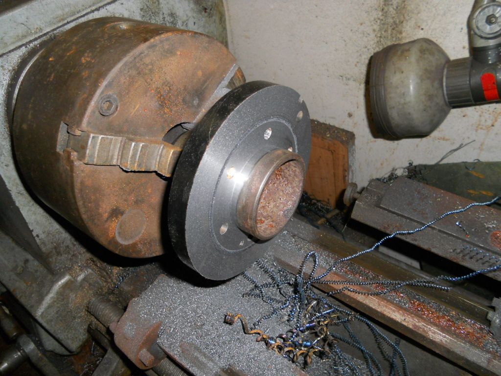
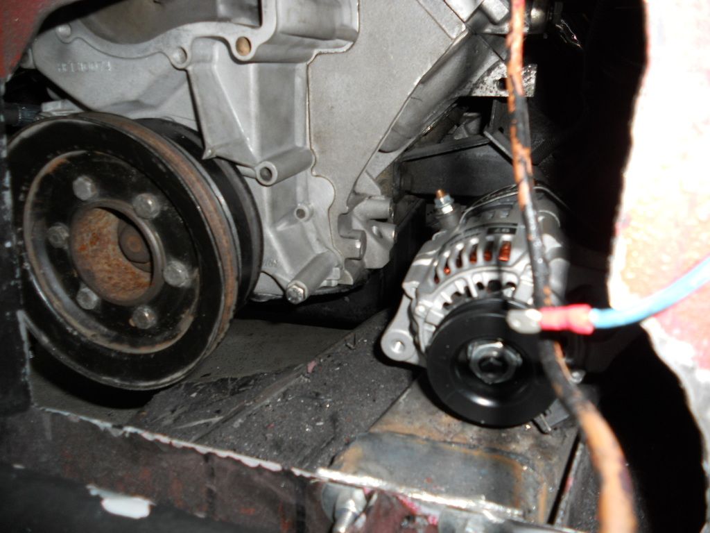
Before I can locate the alternator & bracket, I needed to sort out the bottom crank pulley. This is the serpentine engine however I only intend to
drive the alternator from the crank pulley as there is no need for the power steering and mechanical pump pulleys.
As such, I decided to use the pre-serpentine crank pulley as it is designed for a vee belt instead of the flat belt found on the serpentines. By doing
this, I've got a larger selection of belt sizes to choose from when locating my alternator.
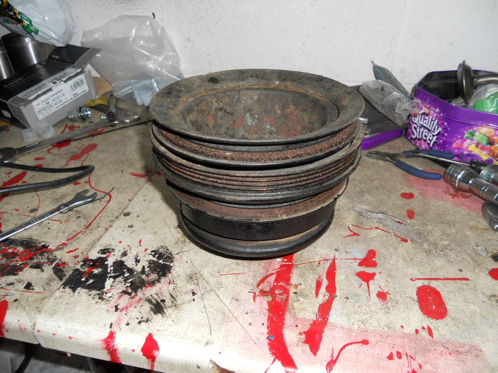
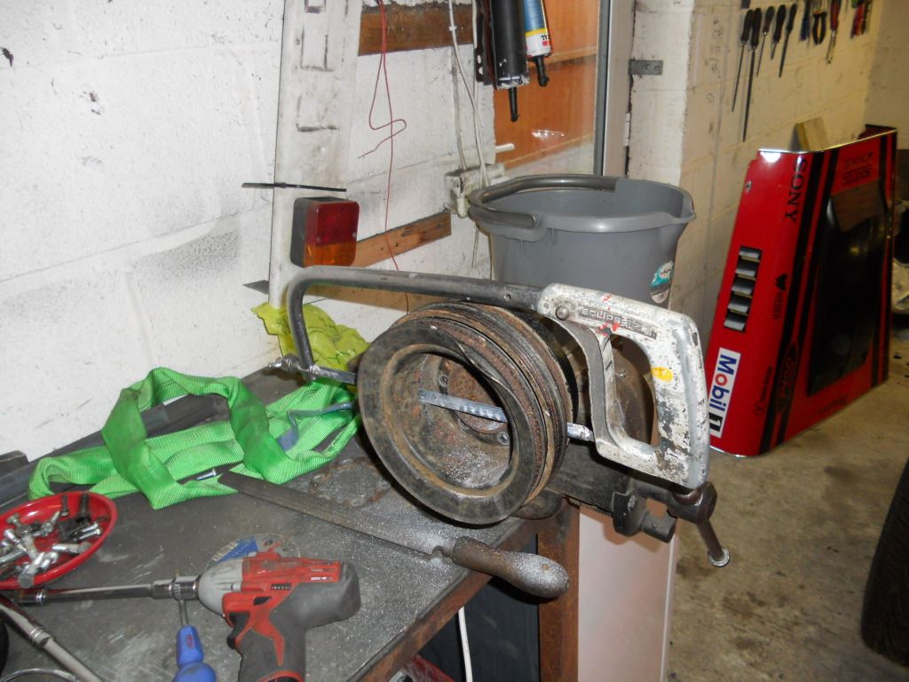
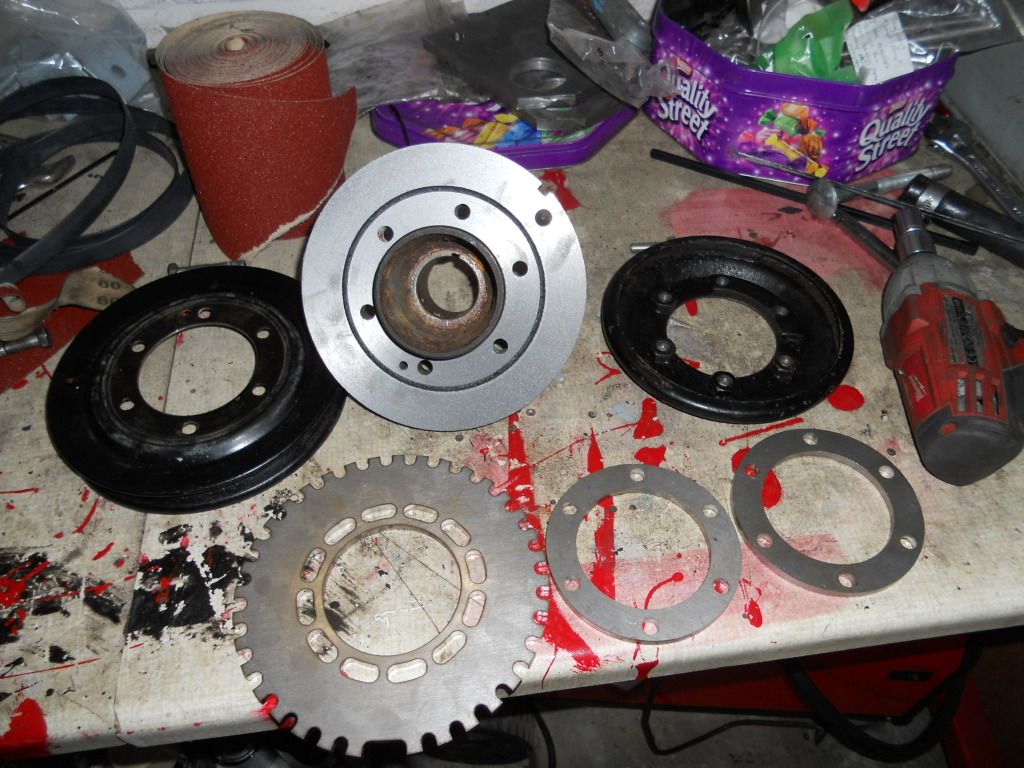
First job was to seperate the pulleys and only 1 pully is needed. This was a swine of a job as the had seized together and so I had to use a hacksaw
to cut them off. Once the had been cut off I could get a screw driver in to prize the rest of the pulleys out.
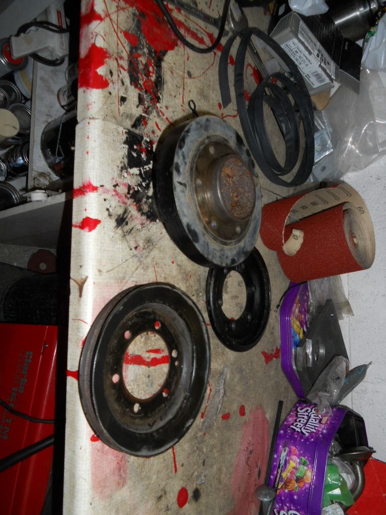
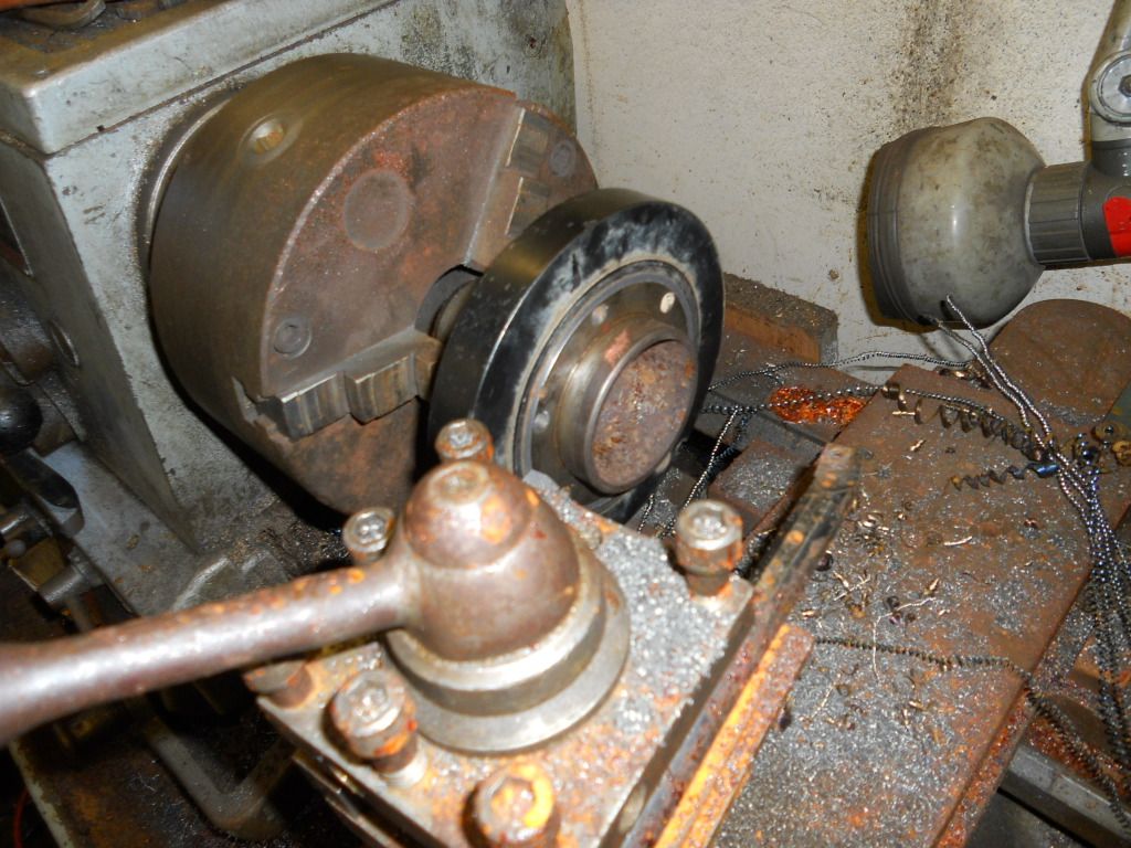
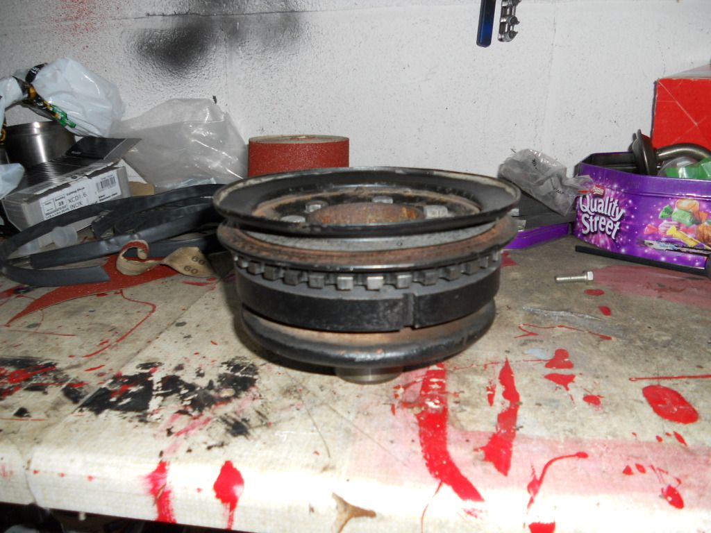
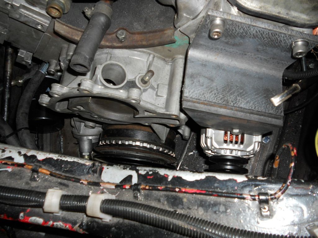
Next is the trigger wheel for the megajolt. I had to do a bit of machining to the main pulley carrier so that I could fit the trigger wheel, 2 spacers
and vee pulley.
|
|
|
sky12042
|
| posted on 27/1/13 at 05:46 PM |
|
|
Looking good m8. Like the exhausts PD Gough done a great job. Would like to hear it running. How about a video of the first start.
Andy.
Ps. if you need any help let me know and I will gladly come round and lend a hand..
|
|
|
richardm6994
|
| posted on 27/1/13 at 07:43 PM |
|
|
Cheers pal. I think it will be a couple of months yet before starting it up!
Pop over for a cuppa anytime
|
|
|
richardm6994
|
| posted on 29/1/13 at 05:54 PM |
|
|
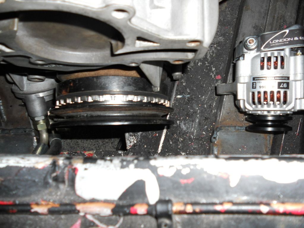
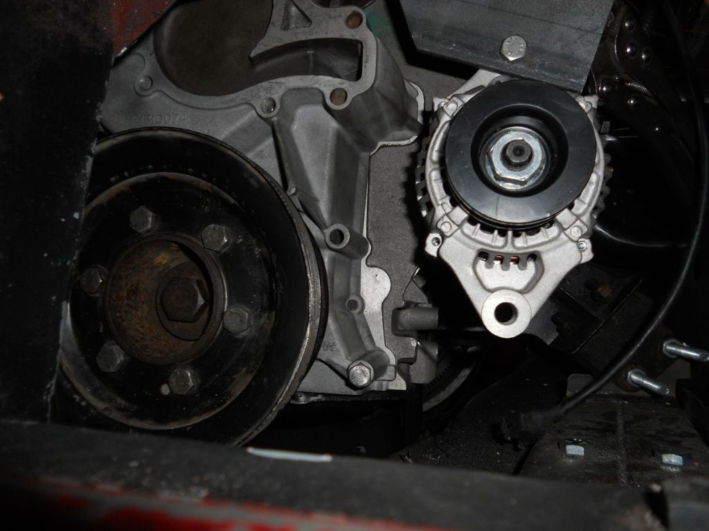
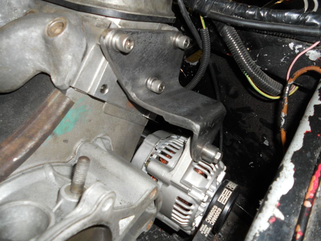
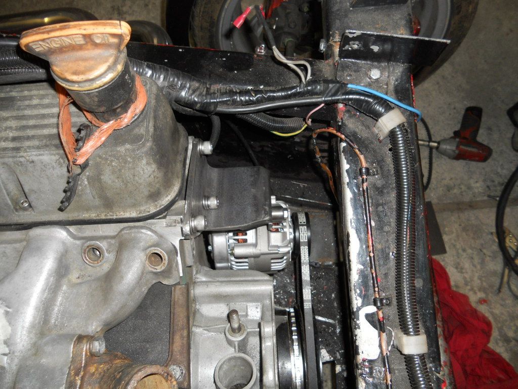
I've got the top alternator bracket mocked-up and the alternator positioned where want it. I didn't want it on top of the engine because
I'd like to keep as much below deck as possible.
Before I go any further, I needed to make sure I can get a vee belt the right size which happens to be 695mm. Once the belt that I've ordered
arrives I'll be able to finish the bracket.
My plan for the bottom bracket is to make it so that I can mount the VR sensor in it plus have a fixing point on it for the belt tension which will be
a threaded adjusters with the rose joints at each end (basically copy the things people sell on ebay for the pinto alternators).
Here is where I'm up to.......
|
|
|
richardm6994
|
| posted on 3/2/13 at 04:15 PM |
|
|
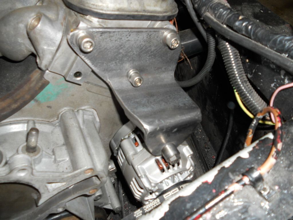
got my top alternator bracket finished today!! I've decided to leave the bottom bracket until the engine is out so I've got better access
to ensure everything lines up etc...
|
|
|
richardm6994
|
| posted on 11/2/13 at 08:06 AM |
|
|
okay..as my goal is to be ready in time for Stonlegh...I really need to get a move on!! So I'm going to increase my time spent on this project
to 2 nights a week and 1 day at the weekend!
Update where I am at;
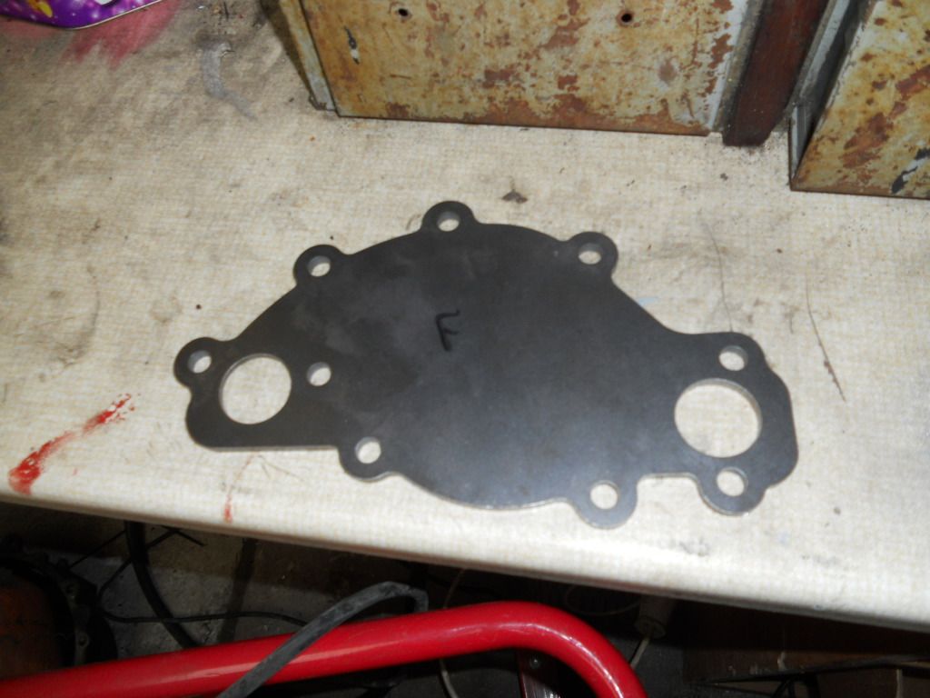
I got the laser cut water pump blanking plate on Friday. It's spot on for fitment onto the engine so I'm dead chuffed.
After a great deal of research regaring mass flow rates (from the ewp spec), pressure drops etc...and also talking to people on the land rover 4x4
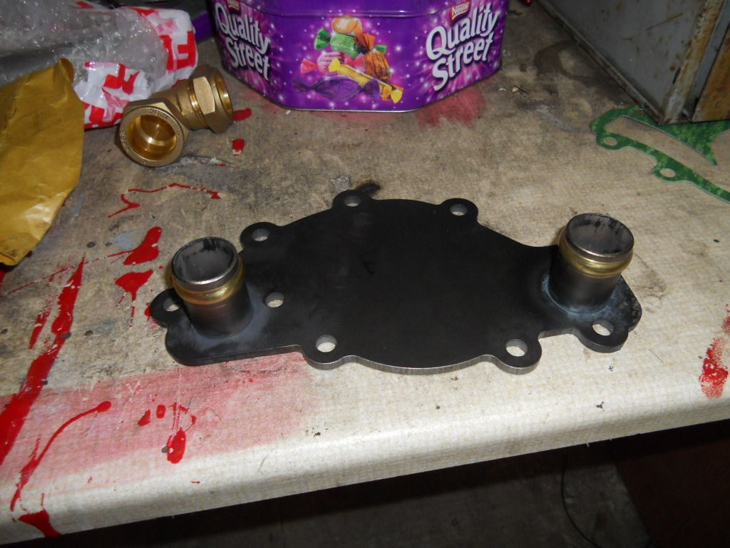
forums, I decided that 2 x 28mm dia inlets would easily be big enough to cope with the max flow rate of 115 litres per minute that the ewp generates
with minimal pressure drop.
So this is the plate to begin with....
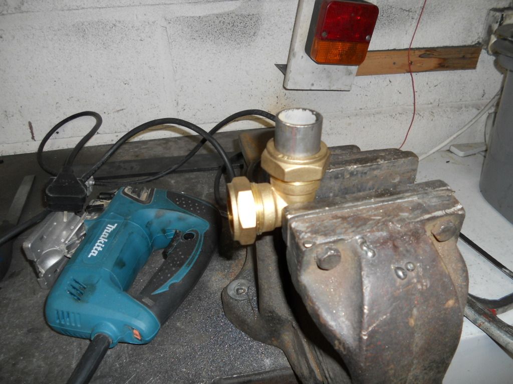
I've crimped a compression fitting olive onto the 28mm dia inlet pipes to act as a flared end to stop the hoses from popping off under
pressure..
Inlets welded onto the plate from the back....I'm going to stick this on the srface grinder to ensure a totally flat sealing face...
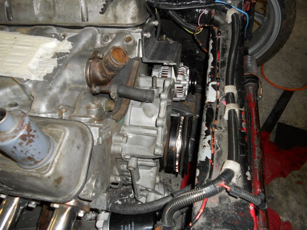
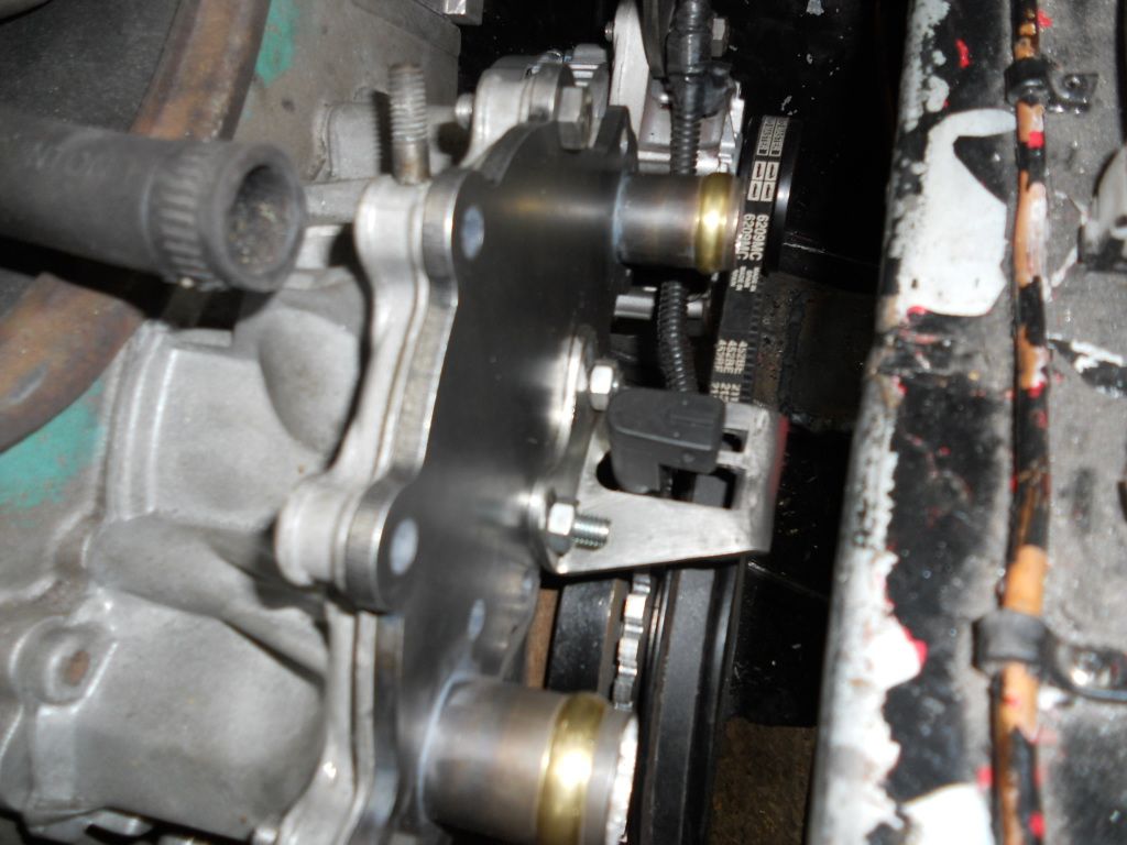
As installed on the engine..I also welded a couple of threaded studs to mount my VR sensor bracket to (I modified the trigger wheels VR bracket to
suit). I've done this to make life a bit easier when it comes to making the bottom alternator bracket
|
|
|
richardm6994
|
| posted on 19/2/13 at 07:49 AM |
|
|
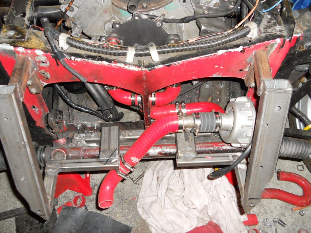
this is where I'm up to.....
Radiator sub frame.
All hoses in situ. More joints than my old university house! When I've finished this project I'm going to save my pennys and get this
fabricated in one peice out of some ally or stainless....but for now this will have to do!
Also the EWP instructions recomend that the unit is mounted to a hose and not bolted to the engine / car. This is to dampen the vibrations.
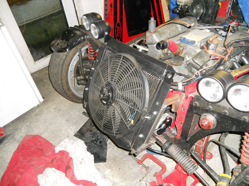
The rad and fan fitted and tested with nosecone fitted. The rad is very deep! 4-cores so this should help keep the v8 lump cool.
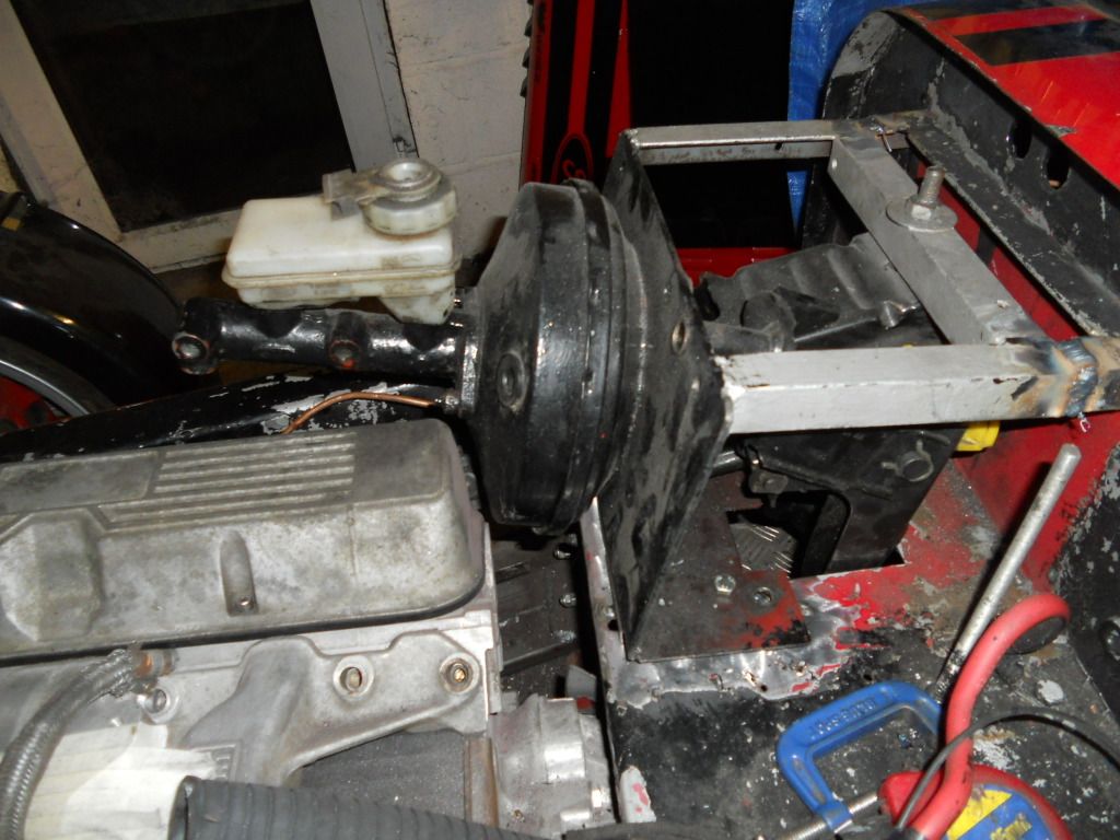
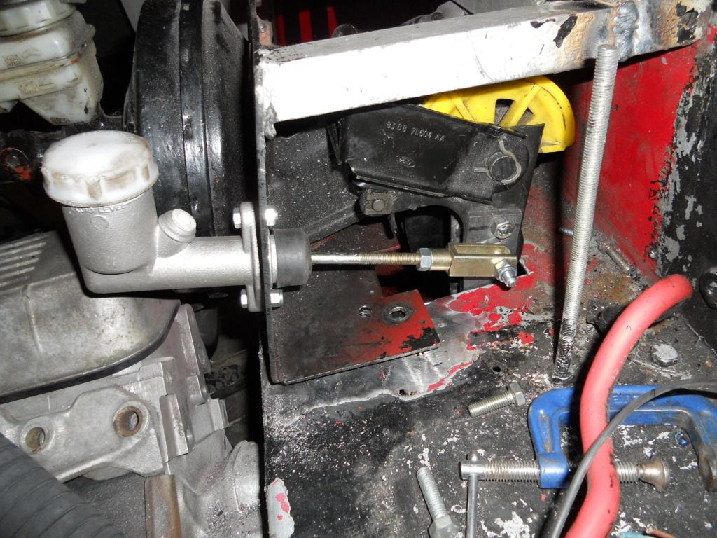
Now onto the pedal box. I've had a play with this and got my original box to fit with the brake servo! theres a good 15-20mm clear to the rocker
cover. I've got a couple of ideas regarding the hydraulic clutch so fingers crossed, this should be a straight forward job
|
|
|
richardm6994
|
| posted on 4/3/13 at 08:38 PM |
|
|
Like a caterpillar eating a cabbage
.hell spend all day eating it but makes bugger all difference to the size of the cabbage.
In model engineering the average build time of a steam engine is 5-10 years so we have lots of days where we do loads of work but the project looks no
further progressed
.so to quote my old man
these are known to us as cabbage-leaf days!!!
The point of this little story is that the last few weeks on the v8 project have been cabbage-leaf days
So this is where Im up to
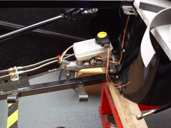
clutch pedal sorted. I've positioned the master cylinder as close to the brake servo as possible so that the centre line of the push rod is as
close to the pedal as possible. The push rod ended up being about 10mm away from the side of the pedal so I didn't think this was too bad.
I've used a short length of 25mm box inside the pedal to prevent the pedal profile from crushing when tightening up the bolts and a 5mm spacer
plate plus m8 nut to set the clevis the correct distance away from the pedal.
Not exactly precision engineering but it's simple enough and it works!
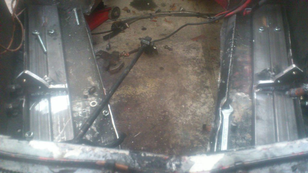
So the next step was to go backwards before I could go any further forwards! I've stripped everything off and taken the engine out. Then
I'm got to sort out my engine wiring, brake lines and paint the engine bay along with loads of other stuff need to be done to finish off the
engine!
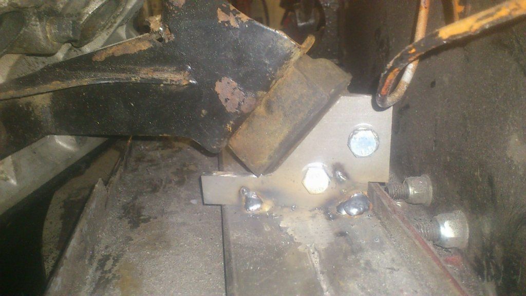
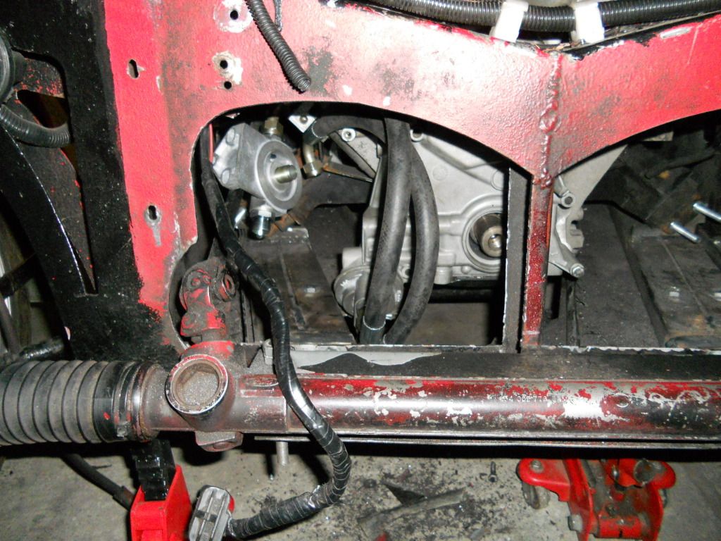
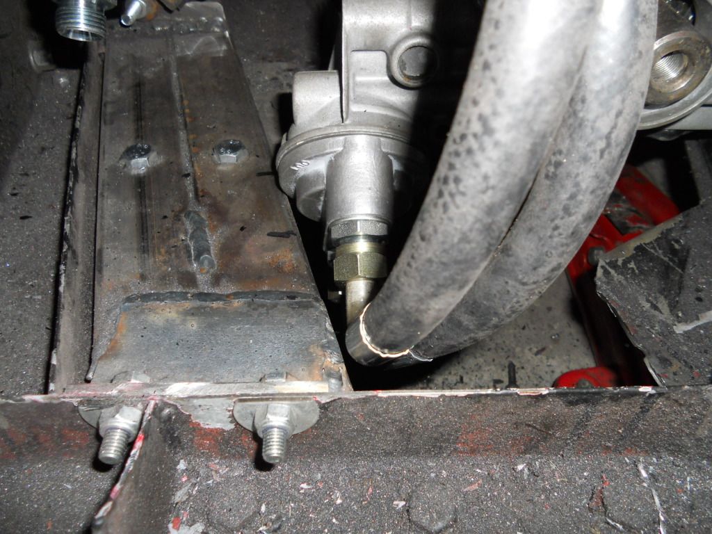
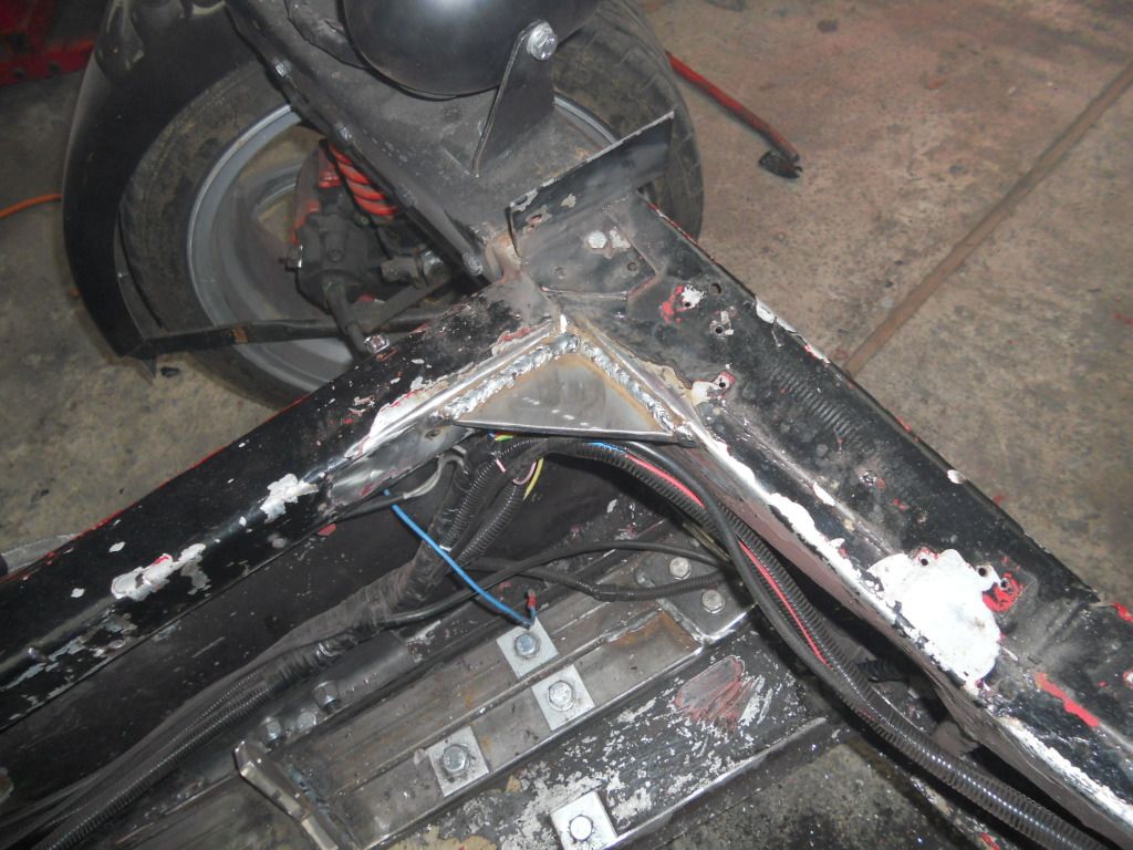
Ive cut the chassis rail and re-welded it to give more clearance between the remote oil filter take-off and the box section (if you look at my
earlier posts youll see that there was hardly any clearance)..
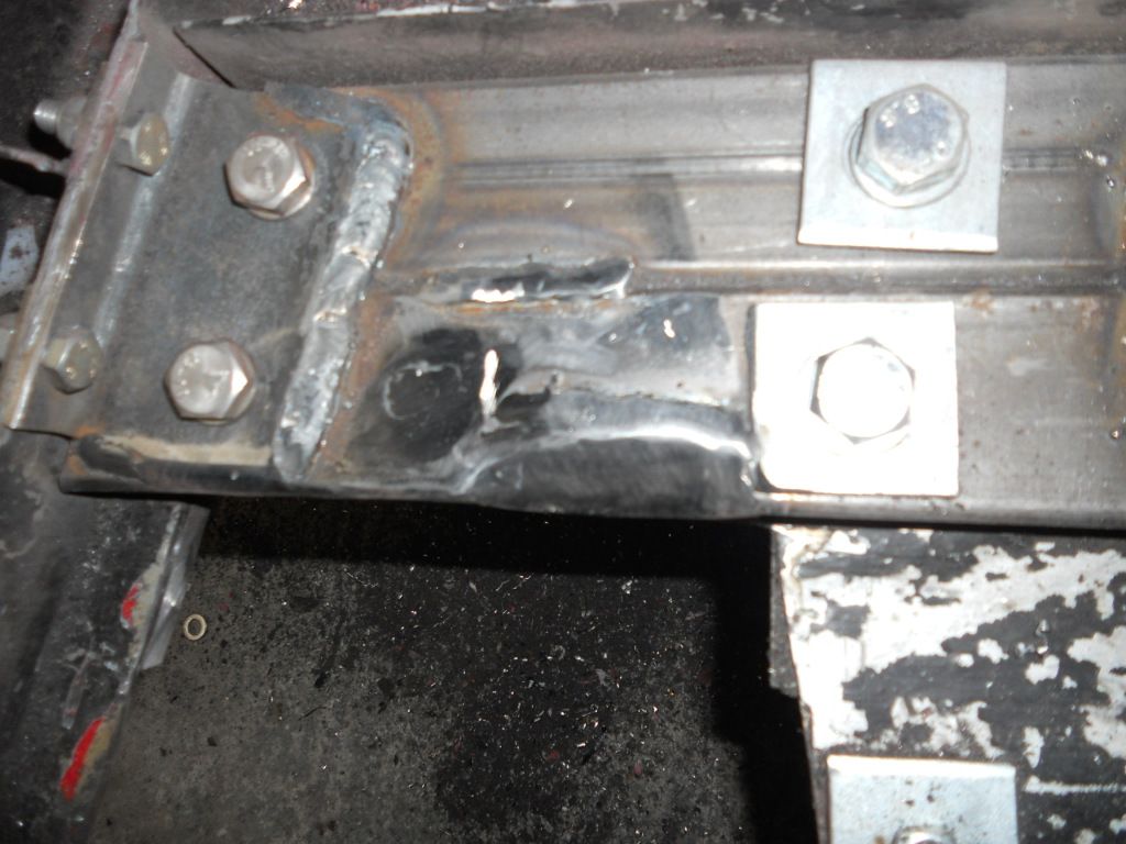
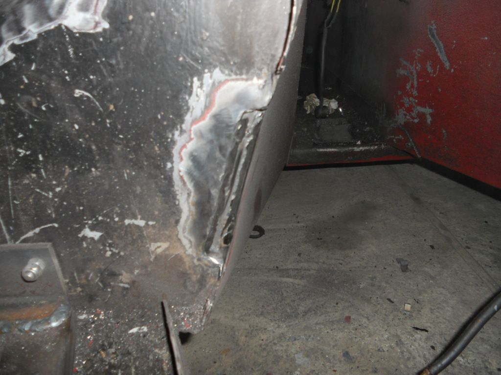
Ive welded up the cut-out which is needed to clear the bell housing..
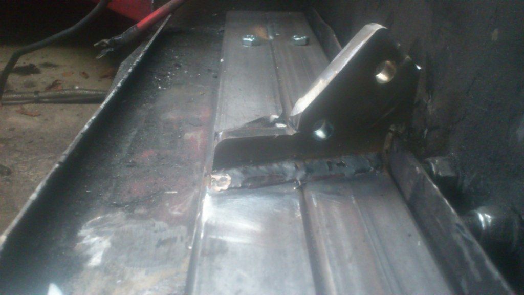
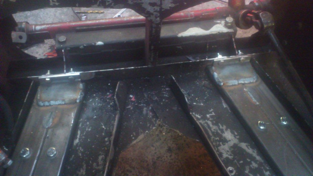
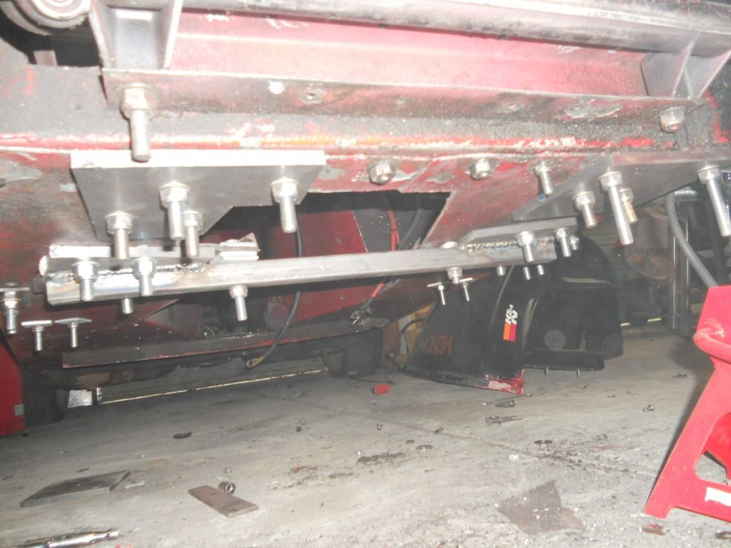
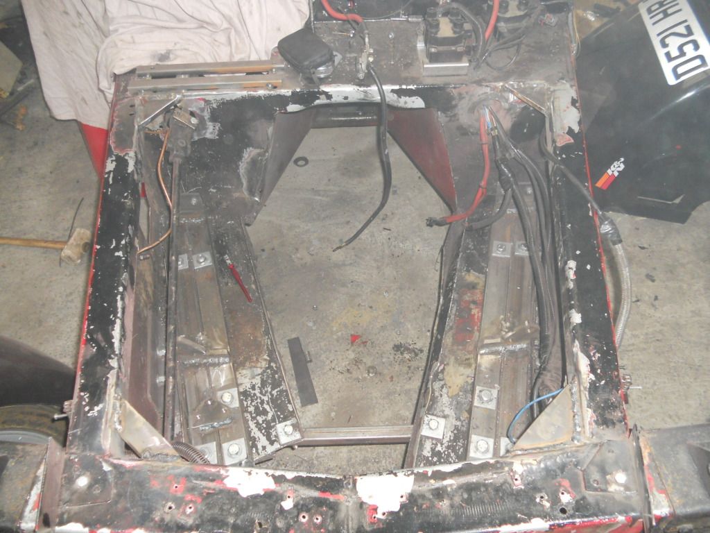
Ive made some plates for the underside of the engine bay to help spread the loads. The plate nearest attach to the end of the box section rails to
the front suspension buttress and the furthest plate haa a piece of 25mm box welded to it to give the engine bay a bit of rigidity
(the bolts will be
cut down in length and new nyloc nuts used)
Ive welded gussets into the corners of the engine bay. The 2 gussets on the drivers side have their corners missing to allow me to route cables and
brake pipes through them
.
|
|
|
Westy1994
|
| posted on 4/3/13 at 09:48 PM |
|
|
I will be interested to see how you get on with the leccy water pump, I have run them for years now on allsorts of cars and they are great. A mate of
mine has fitted a V8 into a Spitfire, but is having overheating issues, I have recommended a leccy pump to help with purging air from the system.
|
|
|
40inches
|
| posted on 5/3/13 at 10:19 AM |
|
|
Some nice work there. Only thing is, I don't think you will need a brake servo. I fitted one to my 2B, it locked the wheels on just about every
minor bump in the road, under braking.
I removed the servo, and moved the brake rod pivot point 25mm nearer the pedal pivot, braking was just about perfect.
The 2B weighed in at 610kilos at SVA, heavier than the Exmo I would think.
|
|
|
richardm6994
|
| posted on 5/3/13 at 12:49 PM |
|
|
Thanks 40inches. It's good to have some feed back cos I was starting to wonder if anyone was reading this 
Regarding the brake servo, I've had similar feedback on the rhocar forum so I'm mindful that this may need to be removed later on down the
line. The reason I've fitted it is simply because it's easy to fit now, see how it performs and if needs be remove it at a later
date....but if it works okay then it's a keeper! (a friend with a v8 westy and servo says it works okay)
|
|
|
scudderfish
|
| posted on 5/3/13 at 01:04 PM |
|
|
I lurk and follow this thread
No servo in my V8 Fury; I did drop a size on the front M/C though. It makes driving a servo assisted car afterwards comedic.
|
|
|
richardm6994
|
| posted on 5/3/13 at 01:09 PM |
|
|
I've got a ford KA m/c as a "plan-b" as I'm led to believe it has a smaller piston than the seirra m/c so this helps to
compensate for the lack of servo.
|
|
|
40inches
|
| posted on 5/3/13 at 02:39 PM |
|
|
quote:
Originally posted by richardm6994
I've got a ford KA m/c as a "plan-b" as I'm led to believe it has a smaller piston than the seirra m/c so this helps to
compensate for the lack of servo.
I have found the Sierra M/C ok, as long as you increase the pedal ratio to around 6:1, or thereabouts 
Description
And a lot more space.
|
|
|
richardm6994
|
| posted on 14/4/13 at 06:45 PM |
|
|
Just a little update to say that the engine bay is done....well at least as done as it needs to be to put the engine back in.
The wiring was finished yesterday so all the engine connections are in the correct places and the brake lines I started and finished today. I only
flared the ends of the pipe and forgot to put the union on twice so not as bad as when I first did the car!!
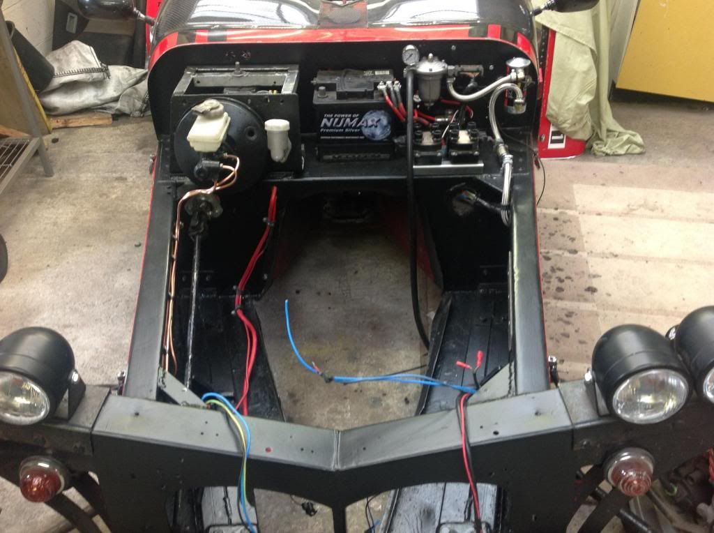
Now it's time to move onto the engine and complete a few job before plonking it back into the car...
Fabricate bottom alternator bracket
Set and pin trigger wheel
Bottom cover plate for the bell house
Clean up gearbox and renew seals and gaskets
Hoses for slave clutch cylinder and remote bleed
|
|
|