JamesyCottony
|
| posted on 4/8/16 at 04:38 PM |

|
|
Hazard Switch
I have been trawling through hundreds of forums and images but I just can't get my head around it all.
What are these numbers?
I know one of he "49" or "49a" is for live and "L" is for left indicator and "R" for right but apart
from that I am lost!?

These are the selection of coloured wire I have:

Please help 
[Edited on 4/8/16 by JamesyCottony]
|
|
|
|
|
gremlin1234
|
| posted on 4/8/16 at 04:53 PM |
|
|
https://en.wikipedia.org/wiki/DIN_72552
edit and colours look lucas standard
http://www.expeditionlandrover.info/Lucaswirecode.htm
[Edited on 4/8/16 by gremlin1234]
|
|
|
JamesyCottony
|
| posted on 4/8/16 at 05:05 PM |
|
|
quote:
Originally posted by gremlin1234
https://en.wikipedia.org/wiki/DIN_72552
edit and colours look lucas standard
http://www.expeditionlandrover.info/Lucaswirecode.htm
[Edited on 4/8/16 by gremlin1234]
Thank you 
So:
-Light Green/Brown to 49
-New wire from 49a to Indicator switch (49 on indicator)
-Green/ Red to L
-Green/ White to R
-Brown to 30
-Brown (From Ignition) to 15 (Why is this needed??)
[Edited on 4/8/16 by JamesyCottony]
|
|
|
gremlin1234
|
| posted on 4/8/16 at 05:19 PM |
|
|
quote:
Originally posted by JamesyCottony
-Brown (From Ignition) to 15 (Why is this needed??)
it should come from the 'ignition switched &fused live', else indicators
will work without the ignition on. (hazards have to work without ignition on)
if I remember the bobcat is based on original mini?
[Edited on 4/8/16 by gremlin1234]
|
|
|
JamesyCottony
|
| posted on 4/8/16 at 05:31 PM |
|
|
quote:
Originally posted by gremlin1234
quote:
Originally posted by JamesyCottony
-Brown (From Ignition) to 15 (Why is this needed??)
it should come from the 'ignition fused switched live', else indicators will
work without the ignition on. (hazards have to work without ignition on)
if I remember the bobcat is based on original mini?
Ahh ok so 15 is for the Accessories ignition wire.....?
It is based on the Metro
If the indicator wires go to the hazard switch, then how does the indicator switch operate the indicators? as there is only 1 wire for left and 1 for
right which go to the hazard switch
|
|
|
gremlin1234
|
| posted on 4/8/16 at 06:03 PM |
|
|
I don't know the wiring for that particular switch / metro
but I would expect the indicator switch to have l & r, as well as the hazard switch having same.
these diagrams may help
http://www.holden.co.uk/wiringDiagrams.asp
[Edited on 4/8/16 by gremlin1234]
|
|
|
Mash
|
| posted on 4/8/16 at 06:12 PM |
|
|
I wired mine using toggle switches using this diagram as I couldn't figure that switch out that you have....
[img]
 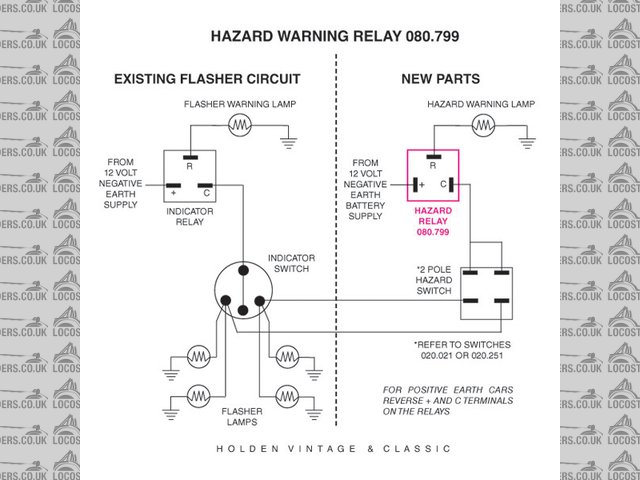
Description
[/img]
Not sure if it will help you but it sort of explains the connection between hazards and indicators
|
|
|
JamesyCottony
|
| posted on 4/8/16 at 06:22 PM |
|
|
So the hazards and the indicators have different relays?
|
|
|
gremlin1234
|
| posted on 4/8/16 at 07:53 PM |
|
|
quote:
Originally posted by JamesyCottony
So the hazards and the indicators have different relays?
there's about 5 different wiring schemes for hazards, and many of these have 2
flasher units, some have diodes, and some just complex switches. (which don't work well with traditional flasher units, since they then flash at
a faster rate.)
|
|
|
tims31
|
| posted on 5/8/16 at 02:08 PM |
|
|
Have a look at my thread about removing the sierra stalk hazard switch and wiring in the Durite hazard switch it may help, has all the wiring and
numbers on it.
http://www.locostbuilders.co.uk/viewthread.php?tid=203699
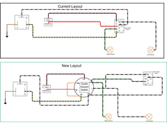 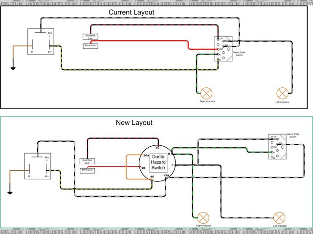
Description
[Edited on 5/8/16 by tims31]
Build: http://www.martinsfurybuild.co.uk/
|
|
|
snowy2
|
| posted on 6/8/16 at 06:18 AM |
|
|
30 is +12v perm live...15 is ignition live l and r is left and right indicator...
or look at this....
Terminal Designations (Excerpts from DIN Standard 72 552) The terminal designations do not identify the conductors, because device with different
terminal designations can be connected at the two ends of each conductor. If the number of terminal designations is not sufficient (multiple-contact
connections), the terminals are consecutively numbered using numbers or letters whose representations of specific functions are not standardized.
Terminal Definition
IGNITION
1 Ignition coil, ignition distributor, low voltage
Ignition distributor with two separate electrical circuits
1a to ignition contact breaker I
1b to ignition contact breaker II
2 short-circuit terminal (magneto ignition)
4 Ignition coil, ignition distributor, high voltage
Ignition distributor with two separate electrical circuits
4a from ignition coil I, terminal 4
4b from ignition coil II, terminal 4
15 Switched + downstream of battery
(output of ignition/driving switch)
15a Output at dropping resistor to ignition coil and starter
GLOW PLUG AND STARTER SWITCH
17 Start
19 Preheat
BATTERY
30 input from + battery terminal, direct
30a input from + terminal of battery II
(12/24 V series-parallel battery switch)
31 Return line to battery - battery terminal or ground, direct
31b Return ine to negative battery terminal or ground, via switch or relay
(switched negative)
(12/24 V series-parallel battery)
31a Return line to - terminal of battery II
31c Return line to - terminal of battery I
ELECTRIC MOTORS
32 Return line
(Polarity reversal possible at terminals 32-33)
33 Main terminal connection
(Polarity reversal possible at terminals 32-33)
33a Self-parking switch-off
33b Shunt field
33f For second lower-speed range
33g For third lower-speed range
33h For fourth lower-speed range
33L Counterclockwise rotation
33R Clockwise rotation
STARTER
45 Separate starter relay output; starter input (main current)
45a Output, starter I
Input, starters I and II (Two-starter parallel operation)
45b Output, starter II (Two-starter parallel operation)
48 Terminal on starter and on start-repeating relay for monitoring starting procedure
TURN SIGNAL FLASHER
49 Input
49a Output
49b Output, second turn-signal circuit
49c Output, third turn-signal circuit
STARTER
50 Starter control (direct)
50a Output for starter control
(Series-parallel battery switch)
50b Starter control with parallel operation of two starters with sequential control
50c Input at starting relay for starter I
(Starting relay for sequential control of the engagement current during parallel operation of two starters)
50d Input at starting relay for starter I
(Starting relay for sequential control of the engagement current during parallel operation of two starters)
50e Input, Start-locking relay
50f Output, Start-locking relay
50g Input, Start-repeating relay
50h Output, Start-repeating relay
ALTERNATOR
51 DC voltage at rectifier
51e DC voltage at rectifier with choke coil for daytime driving
TRAILER SIGNALS
52 Signals from trailer to towing vehicle, general
WIPER MOTOR
53 Wiper motor, input (+)
53a Wiper (+), self-parking switch-off
53b Wiper (shunt winding)
53c Electric windshield-washer pump
53e Wiper (brake winding)
53i Wiper motor with permanent magnet and third brush (for higher speed)
TRAILER SIGNAL
54 For lamp combinations and trailer plug connections
TRAILER STOP LAMP
54g Pneumatic valve for additional retarding brake, electromagnetically actuated
LIGHTING
55 Fog lamps
56 Headlamp
56a High beam, high-beam indicator lamp
56b Low beam
56d Headlamp-flasher contact
57 Side-marker lamp: motorcycles, mopeds. Abroad also cars, trucks, etc.
57a Parking lamp
57L Parking lamp, left
57R Parking lamp, right
58 Side-marker lamps, tail lamps, license-plate lamps and instrument-panel lamps
58b Tail-lamp changeover for single-axle tractors
58c Trailer plug-and-receptacle assembly for single-conductor tail-lamp cable with fuse in trailer
58d Variable-intensity instrument-panel lamp, tail-lamp and side-marker lamp
58L Side-marker lamp, left
58R Side-marker lamp, right; license-plate lamp
ALTERNATOR (magneto, generator)
59 AC voltage, output, rectifier, input
59a Charging armature, output
59b Tail-lamp armature, output
59c Stop-lamp armature, output
61 Alternator charge-indicator lamp
TONE-SEQUENCE CONTROL DEVICE
71 Input
71a Output to horns 1 & 2, low
71b Output to horns 1 & 2, high
72 Alarm switch (rotating beacon)
INTERIOR
75 Radio, cigarette lighter
76 Speaker
77 Door-valve control/td>
SWITCHES
Break-contact and changeover switches
81 Input
81a 1st output, break side
81b 2nd output, break side
Make-contact switches
82 Input
82a 1st output
82b 2nd output
82z 1st input
82y 2nd input
Multiple-position switches
83 Input
83a Output, position 1
83b Output, position 2
83L Output, left-hand position
83R Output, right-hand position
CURRENT RELAY
84 Input, actuator and relay contact
84a Output, actuator
84b Output, relay contact
SWITCHING RELAY
85 Output, actuator (end of winding to ground or negative)
86 Start of winding
86a Start of winding or 1st winding
86b Winding tap or 2nd winding
Relay contact for break and changeover contacts
87 Input
87a 1st output (break side)
87b 2nd output
87c 3rd output
87z 1st input
87y 2nd input
87x 3rd input
Relay contact for make contact
88 Input
Relay contact for make and changeover contacts (make side)
88a 1st output
88b 2nd output
88c 3rd output
Relay contact for make contact
88z 1st input
88y 2nd input
88x 3rd input
ALTERNATOR and VOLTAGE REGULATOR
GENERATOR and GENERATOR REGULATOR
B+ Battery positive
B- Battery negative
D+ Dynamo postive
D- Dynamo negative
DF Dynamo field
DF1 Dynamo field 1
DF2 Dynamo field 2
Alternator with separate rectifier
J Excitation winding positive
K Excitation winding negative
Mp Center point terminal
U,V,W Alternator terminals
DIRECTION INDICATOR (turn-signal flasher)
C First indicator lamp
C0 Main terminal connection for separate indicator circuits actuated by the turn-signal switch
C2 Second indicator lamp
C3 Third indicator lamp (e.g., when towing two trailers)
L Turn-signal lamps, left
R Turn-signal lamps, right
sometimes you are the pigeon, most of the time the statue.
|
|
|
snowy2
|
| posted on 6/8/16 at 06:28 AM |
|
|
I just use a standard DPST toggle switch for a hazard switch.......
they have 6 terminals underneath.....
*1 *2
*3 *4
*5 *6
1 connect to indicator switch lh side
2 connect to indicator switch rh side
3 connect to lh indicator bulbs
4 connect to rh indicator bulbs
5 and 6 connect to each other and to the hazard relay output
sometimes you are the pigeon, most of the time the statue.
|
|
|
JamesyCottony
|
| posted on 6/8/16 at 06:48 AM |
|
|
Thanks for the replies everyone, I will try and work it out :s
|
|
|
JamesyCottony
|
| posted on 13/12/16 at 04:20 PM |
|
|
Still struggling with this....
|
|
|
JamesyCottony
|
| posted on 13/12/16 at 05:11 PM |
|
|
Which one is 30 and which one is b30/30b?
|
|
|
gremlin1234
|
| posted on 13/12/16 at 05:28 PM |
|
|
quote:
Originally posted by JamesyCottony
Which one is 30 and which one is b30/30b?
the letter follows the number
so you have 30b and 30
(ref: see also the terminals 49 and 49a )
|
|
|
JamesyCottony
|
| posted on 13/12/16 at 05:56 PM |
|
|
quote:
Originally posted by gremlin1234
quote:
Originally posted by JamesyCottony
Which one is 30 and which one is b30/30b?
the letter follows the number
so you have 30b and 30
(ref: see also the terminals 49 and 49a )
Thank you, also on the fuse box/relay box there is a space for a 4 pin relay, but there is a 3 pin relay in there, would this be why the indicators
are not working?
|
|
|
gremlin1234
|
| posted on 13/12/16 at 06:06 PM |
|
|
quote:
Thank you, also on the fuse box/relay box there is a space for a 4 pin relay, but there is a 3 pin relay in there, would this be why the
indicators are not working?
quite possible
|
|
|
turnipfarmer
|
| posted on 14/12/16 at 10:21 AM |
|
|
My Sierra loom uses a 19FL-012933 relay for the flashers.
That's only a 3-pin jobbie
Came across this post which might explain how it all works...
http://www.locostbuilders.co.uk/viewthread.php?tid=166135
|
|
|
JamesyCottony
|
| posted on 14/12/16 at 12:36 PM |
|
|
This is where the flasher plugs into:
Fuse Board
This is the flasher:
Flasher
[Edited on 14/12/16 by JamesyCottony]
|
|
|
turnipfarmer
|
| posted on 14/12/16 at 08:58 PM |
|
|
I can find lots of similar round connectors, but not one exactly like that.
Can you find a manufacturer name or code number anywhere on it?
|
|
|