Fred W B
|
| posted on 7/2/05 at 11:29 AM |

|
|
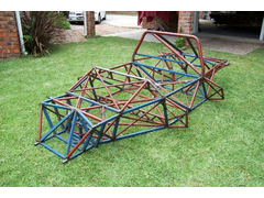
CANAMSA space frame stiffness
Torsional rigidity without side boxes = 2700 ft/lb/Deg
Torsional rigidity with side boxes = 5700 ft/lb/fl/Deg
Result!!!!!!!!!!
See photo's in archive
Cheers
Fred
[Edited on 7/2/05 by Fred W B]
|
|
|
|
|
Fred W B
|
| posted on 7/2/05 at 01:46 PM |
|
|
I seem to having some trouble attaching a photo..................?
|
|
|
JonBowden
|
| posted on 7/2/05 at 02:22 PM |
|
|
Use the browse button at the bottom. Select you file using the Open dialog box that opens.
Note, I have found that if you use the Preview Post button, is drops the image - use tha Post Reply button (ie you cannot preview the post).
Jon
 
Rescued attachment Clipboard.gif
|
|
|
cymtriks
|
| posted on 7/2/05 at 08:41 PM |
|
|
Well done!
A lot of middy chassis are not as stiff as 5700. Or as stiff as 2700 for that matter.
For comparison the Utima chassis weighs about 300lbs and has stiffness of 3300 (coupe) and 2500 (spyder)
|
|
|
kb58
|
| posted on 7/2/05 at 08:50 PM |
|
|
With just a couple extra tubes, one guy got his Ultima up to 10,000.
Mid-engine Locost - http://www.midlana.com
And the book - http://www.lulu.com/shop/kurt-bilinski/midlana/paperback/product-21330662.html
Kimini - a tube-frame, carbon shell, Honda Prelude VTEC mid-engine Mini: http://www.kimini.com
And its book -
http://www.lulu.com/shop/kurt-bilinski/kimini-how-to-design-and-build-a-mid-engine-sports-car-from-scratch/paperback/product-4858803.html
|
|
|
Fred W B
|
| posted on 7/2/05 at 09:02 PM |
|
|
Thanks, Cymtriks
The complete thing weighs about 95 kg's, say 210 pounds
Cheers
Fred WB
|
|
|
sean951
|
| posted on 7/2/05 at 10:56 PM |
|
|
very nice project, i would like to do something similar some day. maybe with a nissan or lexus dual overhead cam V8.
|
|
|
timf
|
| posted on 8/2/05 at 11:39 AM |
|
|
 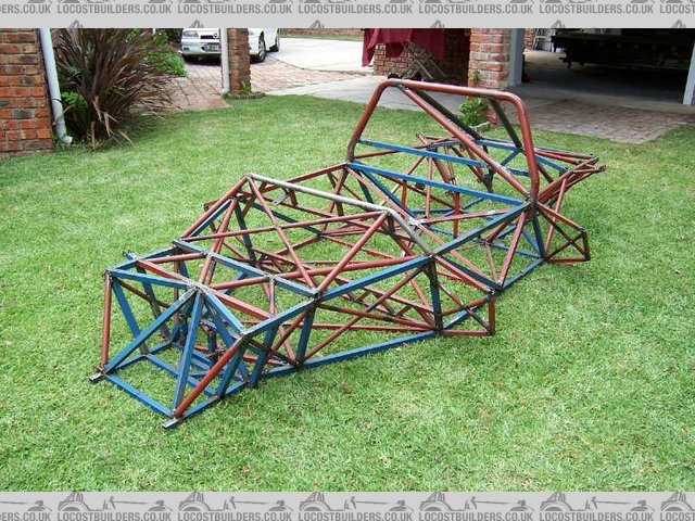
sf canamsa proto front
looks good
|
|
|
Fred W B
|
| posted on 8/2/05 at 11:41 AM |
|
|
Thank you!
|
|
|
imull
|
| posted on 8/2/05 at 07:08 PM |
|
|
out of curiosity, where is the fuel tank going?
excuse me if im being stupid here but its been a long day
|
|
|
MikeR
|
| posted on 8/2/05 at 09:05 PM |
|
|
also how are you going to get your engine in with the rear stays welded in place.
(been wondering that for over a day now!)
actually while i'm wondering, what are you using for uprights & how have you designed your suspension?
|
|
|
Fred W B
|
| posted on 9/2/05 at 06:01 AM |
|
|
To get the engine in, the rear upper space frame/ rear stays section is removable, bolted in at 10 points.
This is still a protoype, with several of the tube joints not properly made, some tube sizes still to be decided, and the joints only partially
welded.
I am now going to buld the car up to running the engine condition in this proto frame, then finally build the real frame and swap all the bits over
Uprights
Firstly cut down and modified Audi front uprights to attach wishbone suspension and get the KPI, castor angle and steering arm length I wanted, but
eventually decided it was getting a bit complicated, so bought some Ford Cortina front uprights. But this may still change.
Rears will be fabricated, around Audi hubs
Suspension:
Currently still in design, as uprights, swingaxle lengths and rollcentre heights are still to be finalized. I may still narrow the rear of the frame
a bit, depending on the final suspension layout
Fuel tank
If you look at some of the mock up pictures in my archive, you will see a V shaped dummy fuel tank in wood (60 liter) and mounted in chassis between
passenger compartment and engine. Held into chassis by removable (from underneath) frame.
|
|
|
v8kid
|
| posted on 10/2/05 at 12:45 PM |
|
|
Great achievement Fred bet there's lots of us wish we were as far on.
How are you aligning the adaptor plate between the rover engine and the audi gearbox? I assume it has to be pretty accurate to plus or minus a thou or
so? I tried a dummy run with a thin ally sheet by by alligning the plate to the 'box with an input shaft size hole in the plate, fixing the
plate to the box and then lining up the box and plate to the crank spiggot. There was so much slack though that the end result was mince - about 15
thou variation in each direction.
Is the input shaft on the box long enough to engage in the crank spiggot with a thicker ally sheet? - so many questions eh!
Also are you intending to bolt the adaptor plate directly to the chassis and make it serve a dual function as an extra stiffening bulkhead? I worried
about the effect of the vibration on the chassis welds - I know the bike engine chaps do it but they don't have V8's rumbling away behind
their heads.
Cheers
David Child
|
|
|
Fred W B
|
| posted on 10/2/05 at 01:39 PM |
|
|
Good questions Dave, and some are things I am still grappling with.
I have drawn up and am having a flywheel made, which essentially looks like the Rover flywheel on the engine side, and the Audi flywheel on the
gearbox side (with scallops to lighten it). This ends up quite long (66mm in total), so to keep the adaptor plate down to a thickness of 20 mm, the
ring gear actually runs in a recess in the thickness of the adaptor plate, and the heads of the gearbox side bolts are countersunk and fixed to the
adaptor plate, as they fit inside the OD of the ring gear, if that make sense. I have also positioned the ring gear closer to the engine than on the
standard Rover, to the extent of having to relieve slightly some of the casting webs on the back of the block. Doing this, the gearbox input shaft
still fits into the end of the crank, but will need a stepped spigot bush made up.
As for aligning the adaptor plate, I am planning to dowel the assembly together, but haven't quite worked out how to set it up yet. I hope by
assembling the parts and using spacers, dial gauges etc and referencing off the flywheel I can get it right, and then drill all three parts, or
something...
All along I have been planning to use the adaptor plate as a rear bulkhead, and bolt in in solid (although retain the standard front engine rubber
mounts). I can then mount the front legs of the rear wishbones right adjacent to it, and also use it to stiffen the rear chassis.
I was surprised to find though, when testing the torsion stiffness both with and without it, that it made very little different to the pure torsion
stiffness. I used 2 diagional cross braces tacked in to represent it, the part in the photo's is a wooden dummy.
And several people have remarked on the vibrations aspect. But how bad can it be, when the V8 probably not go much above 6 thou, and I am used to 2
stroke karts? So I am still undecided on this one - Any further comment anyone?
Cheers
Fred WB.
|
|
|
cymtriks
|
| posted on 11/2/05 at 07:11 PM |
|
|
Probably simpler and lighter to use a standard design of adaptor plate, run a couple of tubes around the chassis to restore the stiffness and mount
the engine on its intended rubber bushes.
It's generally not a good idea to solid mount an engine for a road car or even for a race car unless you have the resources to assess the impact
of this on vibration and the engine itself.
|
|
|
JonBowden
|
| posted on 12/2/05 at 01:12 AM |
|
|
quote:
It's generally not a good idea to solid mount an engine for a road car or even for a race car unless you have the resources to assess the impact
of this on vibration and the engine itself.
why - didn't lotus do this on the type 49 ?
Jon
|
|
|
kb58
|
| posted on 12/2/05 at 02:43 AM |
|
|
I believe a direct engine-to-chassis connection is usually seen on real race cars.
Are you building a track-only car that will be stripped down and rebuild *at least* every race season? I think that's what real race teams do.
That and tons of research into vibration and stress analysis. I think that's the only way to make sure the vibration doesn't break
anything.
Mid-engine Locost - http://www.midlana.com
And the book - http://www.lulu.com/shop/kurt-bilinski/midlana/paperback/product-21330662.html
Kimini - a tube-frame, carbon shell, Honda Prelude VTEC mid-engine Mini: http://www.kimini.com
And its book -
http://www.lulu.com/shop/kurt-bilinski/kimini-how-to-design-and-build-a-mid-engine-sports-car-from-scratch/paperback/product-4858803.html
|
|
|
v8kid
|
| posted on 15/2/05 at 03:45 PM |
|
|
There's more than just the global chassis stiffness to consider with solid alloy bulkheads.
Mountings for spring rocker arms, upper and lower forward wishbones which are rigid and in the same plane (no local bending loads) are very difficult
to fabricate. Also the precision which machined alloy plates give makes setup a breeze - well a bit easier anyhow.
Also makes a handy mounting point for reversed starter motors when using smaller diameter flywheels. On this theme the whole point about mid
engined cars is weight distribution to take advantage of powerfull engines and to get round corners quickly. Hang on, hang on, I'm getting
to the point - that means dry sumping and mounting the gearbox upside down to get low c of g and reasonable driveshaft angles. So we are back to
fabricating special adaptors anyhow.
Having gone so far it seems pointless to use the existing rubber engine mounts - might as well mount them rigidly also
1/2 inch routers and tungstone carbide bits are so cheap that machininmg costs are negligible and good fun to try.
Despite all these advantages it intuitively feels wrong to mount an engine solidly - preconceived ideas I know but hard to shift.
Has anyone any experirnce of using solidly mounted engines in a road/track day car sucessfully?
|
|
|
wheelsinsteadofhooves
|
| posted on 15/2/05 at 04:42 PM |
|
|
have some experiance re engine/chassis without rubber from designing/building formula student car at uni.
slight differece though in that that used 600cc honda motorbike engine that revved way high. it vibrated like a b*****d at low revs (also not much by
way of seat), but wasnt too bad when going nicely. not really recommended for everyday driving though, as the vibrations from an normal 4 stroke trend
to be around the natural frequencies of nut/bolt interfaces. ie your car will eventually shake apart if not loctited/ lockwired (both is done
simultaneously on race cars) nylock not going to cut it alone.
solid mountings are used on race cars as its all about efficincy and predicatability of transmission of forces. rubber deflects under cornering etc,
altering c.o.g., thereby chaning behavioral characterisitcs of car. fine for road car but looses valueable 1/1000s of seconds on the track.
the choice is yours, but don't underestimate the destructive effect of low/mid range (engine) vibrations, on your spine too.
speaking of efficiency intransmission of forces, this is what a chassis is all about. that pictured looks great but some inefficincies (ie redundant
members). the side bracing (2 diags) stands out (1 longer diag = same/better rigidity but less steel). just extra weight, but has merit has crash
protection. just a point. great chassis though, do indeed wish i was that far on!!
[Edited on 15/2/05 by wheelsinsteadofhooves]
|
|
|
Fred W B
|
| posted on 15/2/05 at 07:28 PM |
|
|
Thanks for further input guys.
I am tempted to continue with the solid mounting of the full plate, at least in the proto build up and systems checks. If it does seem to buzz badly I
can still cut the bulkhead into an inner adaptor plate and outer chassis ring , possibly bonded together with urethane?
I like the engineering simplicity of the solid plate, and as I am using inboard rear brakes, it make mounting the calipers much simpler if the whole
transaxle is solid in the frame, which will also add to the stiffness where the rear wishbones attach.
Maybe I'm wrong, but if ordinary MIG welds and loctite can keep a very flexable kart chassis together while a solid mount two stoke is running
at up to 16 000RPM,
I want to at least try it with the V8. And I ran that kart for 3 years, in one of which I ran the kart on 40 different days!
Out here we run front engined race classes with tube frame chassis and v8 and opel two litre engines solid mounted by means of alloy plates bolted
across the front of the engines, NASCAR style, and those don't seem to give trouble.
I am building the car to work well on the track, and do some limited running on the road, and I like to keep my toys clean, so I will hopefully spot
any cracking if it occurs. I will also add gussets to the tube juctions around the mounting plate.
With regard to the twin diagionals next to your legs. As the dash bulkhead leans forward at 10 degrees, the side is not a true flat plane, hence the
two diags.
Rereading the above, I hope I am not giving the impression that whenever someone suggests something I want to shoot it down, I am very gratefull for
the input.
As has been stated in some other threads before, the most valuble info comes from people who have done similar things before, and people who have done
that are few and far between out here.
Cheers
Fred WB
|
|
|
krlthms
|
| posted on 15/2/05 at 10:16 PM |
|
|
Fred,
Not withstanding the comment about people who have done things previously knowing best, have you thought about the engine end of things. Can your
engine design tolerate the engine being a stressed member? As you say repairing a cracked mounting is easy enough, but how about a cracked engine
block? I don't think the comparison of a hefty V8 with a two stroke moto-engine is very helpful; the torques involved are not even in the same
order-of magnitude.
I found this article helpful a while ago when I was thinking about solid mounting engine and gearbox.
http://www.e31.net/engines_e.html
Cheers
KT
|
|
|
Fred W B
|
| posted on 16/2/05 at 10:28 AM |
|
|
I am not stressing the engine. I still have a full frame around the engine. The rear of the engine is held in the frame by the ababtor plate bulkhead,
while the front of the engine will be mounted on the original rubber mounts.
Fred
|
|
|
RallyHarry
|
| posted on 16/2/05 at 10:44 AM |
|
|
http://www.e31.net/engines_e.html
great, really shows why I should use a boxer (Subaru) engine :-)
|
|
|
cymtriks
|
| posted on 16/2/05 at 09:00 PM |
|
|
The sides of the seat area and of the footwells only need one diagonal each. That means you can lose four tubes.
The top of the footwell is braced by an X and by two side diagonals under the X. You don't need the side diagonals. The W over the bit infront
of the footwell could be replaced by a V brace pointing forwards.
There does seem to be a lot of tubes around the front suspension. Compare it with a Locost chassis. You could take a lot of the weight out in this
area.
|
|
|
Fred W B
|
| posted on 17/2/05 at 07:22 AM |
|
|
Points taken. I do intend to simplify the front once I have finalized the front suspension.
Cheers
Fred WB
|
|
|