niceperson709
|
| posted on 26/7/05 at 06:29 AM |

|
|
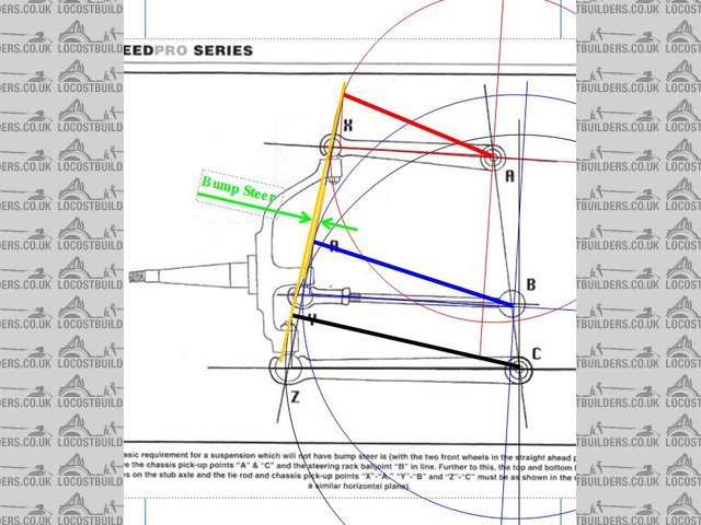
steering issues
Hi Folks
Im in the process of sorting out my steering and just want some reasurance that I am on the right track . My car is 2 inches wider than the book and I
am using Toyota Lite ace uprights . because the original steering arms are to long I have a set of Mk 1 escort steering arms .
Having sorted out the A arms and uprights I have the rack mounted higher than is usual so that the tie rod ball joints are in line with the
suspension piviots as per the diagram below .this puts my rack about half way between the top and bottom A arms . I had thought that I could get
away with just turning the escort steering arms upside down and swaped over left to right and vica versa . But now it seems that I will have to space
them inwards from the uprights so the actual ball joint is closer to the line between the upper and lower ball joints . Does this sound right ? All of
this is the result of trying to avoid cutting down the rack and to achieve zero bump steer
best wishes
Iain+
++
+++
Best wishes IAIN
life is not the rehearsal , it's the show so don't sit there thinking about it DO IT NOW
http://iainseven.wordpress.com/

|
|
|
|
|
niceperson709
|
| posted on 26/7/05 at 06:30 AM |
|
|
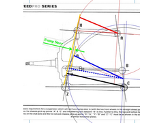
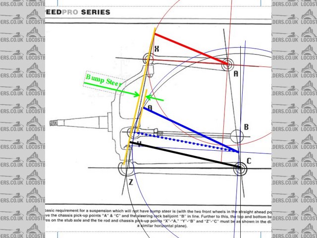
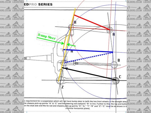
here is the scematic
 
Rescued attachment NO_BUMP s.jpg
Best wishes IAIN
life is not the rehearsal , it's the show so don't sit there thinking about it DO IT NOW
http://iainseven.wordpress.com/
|
|
|
niceperson709
|
| posted on 26/7/05 at 06:42 AM |
|
|
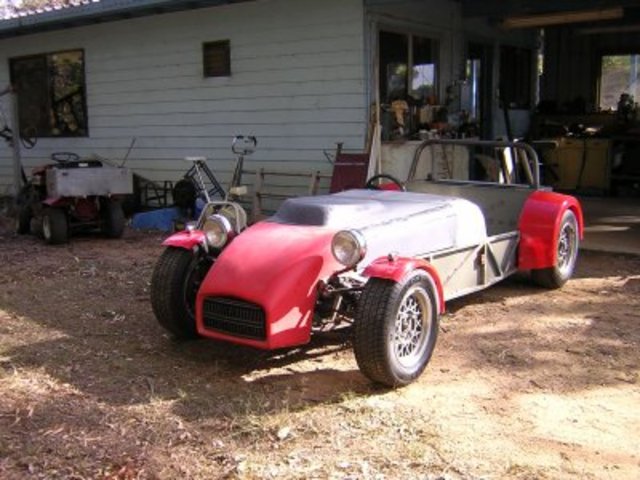
here is a pic of the layout of the front end
Best wishes
Iain
 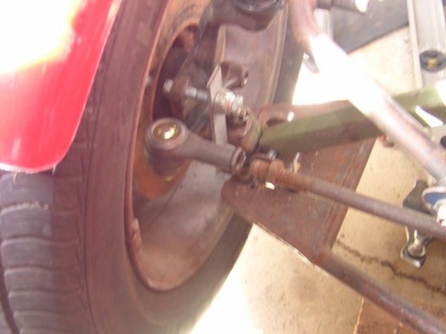
Rescued attachment Dscn0842s.jpg
Best wishes IAIN
life is not the rehearsal , it's the show so don't sit there thinking about it DO IT NOW
http://iainseven.wordpress.com/
|
|
|
JoelP
|
| posted on 26/7/05 at 07:31 AM |
|
|
whilst i cant guarantee good results, you certainly appear to be very much on the right track. 
|
|
|
Fred W B
|
| posted on 26/7/05 at 08:33 AM |
|
|
Staniforth and others also recommend keeping the ratio of AB to BC the same as the ratio of XY to YZ, in your diagramm
Cheers
Fred W B
|
|
|
MikeR
|
| posted on 26/7/05 at 07:04 PM |
|
|
any idea what a toyota lite ace is in the uk ??
|
|
|
JoelP
|
| posted on 26/7/05 at 07:22 PM |
|
|
one of those tiny vans

|
|
|
MikeR
|
| posted on 26/7/05 at 09:22 PM |
|
|
hmmm, sure we had them, haven't got a clue what they where called over here tho.
|
|
|
niceperson709
|
| posted on 27/7/05 at 05:59 AM |
|
|
"any idea what a toyota lite ace is in the uk ??"
I believe that they may have been called Prievia as they were in the states . There was also a version called the Hi-Ace which usually had five stud
wheels but the uprights were the same . I used a Lite ace as the running gear Donor for my build and I wanted to keep the brakes matched , and as I
have used the entire braking system (including booster and proportioning valve )
"Staniforth and others also recommend keeping the ratio of AB to BC the same as the ratio of XY to YZ, in your diagramm "
I must be thick but I don"t quite understand this please explain further ........

this is a Hi ace upright , same as a Lite ace
Best wishes
IainImage deleted by owner
Best wishes IAIN
life is not the rehearsal , it's the show so don't sit there thinking about it DO IT NOW
http://iainseven.wordpress.com/
|
|
|
AGK7
|
| posted on 27/7/05 at 07:50 AM |
|
|
quote:
"Staniforth and others also recommend keeping the ratio of AB to BC the same as the ratio of XY to YZ, in your diagramm "
I must be thick but I don"t quite understand this please explain further ........
This is much the same as the comment on the bottom of the pic.
"Further to this the top and bottom ball joint centres on the stub axle and the tie rod and chassis pick up points "X"-"A"
"Y"-"B" and "Z"-"C" must be as shown in the diagram) in a similar horizontal plan)"
I think if you got your compass out and started drawing arcs off the chassi pic up points one would see how the steering can be "self steer"
as the wheel moves up and down. I have tried to explain it in the following pics
Normal Rack 
Normal Steering Rack
With the rack lower
Low Steering Rack
and higher
High Steering Rack
Hope this helps, i have actually been meaning to have a look at this for my own benifit for some time so thanks for the kick
As i understand the only way to absolutely remove bump steer is to either have the steering arm and rack level with either the top or bottom wishbone
thus having the exactly the same arc. Hope this helps, could be all wrond but it seems to work.
Cheers
Andrew
|
|
|
niceperson709
|
| posted on 27/7/05 at 08:21 AM |
|
|
Hi Andrew
So if I read this right you are saying that not only should the tie rod should be parralell to the a line between the piviots of the bottom a arm and
the lower ball joint and the tie rod balljoint should be also on the same vertical axis as the uprights uper and lower balljoints .
Best wishes
Iain
Best wishes IAIN
life is not the rehearsal , it's the show so don't sit there thinking about it DO IT NOW
http://iainseven.wordpress.com/
|
|
|
AGK7
|
| posted on 28/7/05 at 10:55 PM |
|
|
Iain,
Stick with me i am only learning all of this myself. I am not quite sure what you are asking but have attached below an extract from good old
Staniforth were he offers two methods of setting up to avoid bump steer.
Let me know if this helps.
 
Staniforth Bump Steer
Cheers
Andrew K
Albury, Australia
|
|
|
niceperson709
|
| posted on 28/7/05 at 11:20 PM |
|
|
Hi Andrew
thanks for the diagram Is there any chance that you could post the acompaning text from Stainforth ? I have read some of his stuff and it is generally
good but I do not have a copy of his book.
I think I havea handle on the things to do to solve this particular problem . my rack has its piviots in line with the suspension piviots and I can
vary the location od the steering arms . If all else fails I can have my rack shortened and have the steering arms in a more usual position but I will
see if I can make it work where it is first .
As you will be aware here in OZ they want virtually zero bump steer but the boys in blighty can get away with more
best wishes
Iain
Best wishes IAIN
life is not the rehearsal , it's the show so don't sit there thinking about it DO IT NOW
http://iainseven.wordpress.com/
|
|
|
AGK7
|
| posted on 29/7/05 at 12:02 AM |
|
|
Iain,
Your have U2U
Cheers
Andrew K
Albury, Australia
|
|
|
MikeRJ
|
| posted on 29/7/05 at 02:22 PM |
|
|
Ian,
Slightly OT but those wishbones suffer from a huge stress raiser, worse than the standard book design as you have a bar welded accross rather than
just a plate, and also the wishbone looks wider at this point which makes matters worse.
Your shock mounting is nice and close to the the bottom ball joint to minimise bending moments in bump, but there is still the potential for failure
under braking.
|
|
|
niceperson709
|
| posted on 29/7/05 at 10:48 PM |
|
|
Hi Mike
I do understand what you are saying but also my wish bones are made of 3mm thick seamless tube so subsantially stronger than the book design . they
are tig welded and wider because I am using the stock toyota lite ace bottom ball joint .As you point out my suspension mount is very close to the
outer end and this will mean less bending force on the A arm .Having seen some book A arms and read the myriad of posts about their failure I am
pretty sure mine will be up to the job
best wishes
Iain
Best wishes IAIN
life is not the rehearsal , it's the show so don't sit there thinking about it DO IT NOW
http://iainseven.wordpress.com/
|
|
|
violentblue
|
| posted on 26/8/05 at 04:27 AM |
|
|
Now these are the formulas that I've been searching for for ages. My instincts were telling me thats how it ought to be done, but I really
didn't know for sure.
No anyone have the formulas how to set up Ackerman? I got some ideas How I think it should be, but goptta make sure its right.
a few pics of my other projects
|
|
|
niceperson709
|
| posted on 26/8/05 at 05:01 AM |
|
|
Hi folks
an update on my progress I have now finished the adaptors to conect the steering arms to the up rights bsicly four pieces of 12 mm steel drilled to
match the mounting holes ion the uprights and drilled and tapped so the steering arms can be bolted to them . once put together I used a laser pointer
held on to a wheels stud so that it shon onto some graph paper taped to the wall 800 mmm away the position at full droop and full bump were plotted
and a line drawn between them and then I raised the suspension progressively in 10 mm steps and plotted the positions over the whole travel no point
was more than 2mm forward of the line I plotted . which i think adds up to a very small deviation indeed. I can't do the math but it seems to me
that given the distance from the axel end to the graph paper it must be a lot less than a degree over the full travel.
With regaurd to Ackerman angles I don't know some say it is crucial some say all it will mean if it is wron is higher tyre wear , but on a light
car that is not going to matter that much.
Rescued attachment three quarterfront.jpg
Best wishes IAIN
life is not the rehearsal , it's the show so don't sit there thinking about it DO IT NOW
http://iainseven.wordpress.com/
|
|
|