Fred W B
|
| posted on 24/12/05 at 12:25 PM |

|
|
Attention Suparuss - Audi 016 trans gearshift pattern?
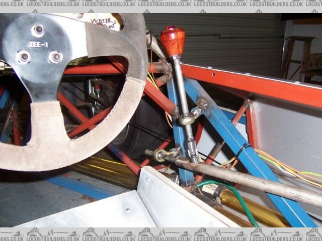
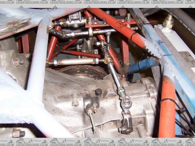
I have mocked up my gearshift linkage in my proto chassis (see below) and I have a question that I am sure Suparuss can answer.
As I have never seen the Audi 016 transaxle gear linkage in a donor car, I am unsure what the shift pattern is.
I have guessed as follows:
Looking at the box from the (car) rear, shift actuator input is on left hand side, with lever pointing straight upwards.
Move actuator to left, push lever forwards = 1st
Move actuator to left, pull lever backwards = 2nd
Actuator in center (neutral) position, push lever forwards = 3rd
Actuator in center (neutral) position, pull lever backwards = 4th
Move actuator to right, push lever forwards = 5th
Move actuator to right, pull lever backwards = reverse
Is this correct? If not, what is the correct pattern?
Cheers and Merry Christmas
Fred WB
 
linkage 1 25%
gear lever
[Edited on 24/12/05 by Fred W B]
|
|
|
|
|
kb58
|
| posted on 24/12/05 at 03:57 PM |
|
|
Maybe I'm on drugs, but I can't see how that linkage can possible work. Moving the shifter up and down (toward and away from you) it
looks like it would work fine. But I can's see how it can possibly move left or right...
I think you'd have to eliminate the upper bearing to get the motion you need.
[Edited on 12/24/05 by kb58]
Mid-engine Locost - http://www.midlana.com
And the book - http://www.lulu.com/shop/kurt-bilinski/midlana/paperback/product-21330662.html
Kimini - a tube-frame, carbon shell, Honda Prelude VTEC mid-engine Mini: http://www.kimini.com
And its book -
http://www.lulu.com/shop/kurt-bilinski/kimini-how-to-design-and-build-a-mid-engine-sports-car-from-scratch/paperback/product-4858803.html
|
|
|
suparuss
|
| posted on 24/12/05 at 04:11 PM |
|
|
looks fine to me, that extra joint at the bottom will act as a pivot to spin the main shaft.
that pattern is exactly how it was in the car fred, so it depends if there are any levers reversing the movements, in the car- the foreward backward
movements were reversed and left right remained the same (if i remember correctly) 
you should be able to figure it out from there i think.
Russ.
|
|
|
Fred W B
|
| posted on 24/12/05 at 04:18 PM |
|
|
Hay Kurt
No, you are not on drugs, I should have included the picture below which shows the lever that gives the left/right movement to the actuator. It looks
short, but the actuator in the box only moves 6 mm to left and right.
It does work fine, although the left/right effort on the gear knob is a bit high. I am thinking about a linkage to give some mechanical advantage in
the LR movement.
Cheers
Fred WB
linkage 2
|
|
|
Fred W B
|
| posted on 24/12/05 at 04:25 PM |
|
|
Hi Russ, I was taking the photo above when you replied.
Thanks a lot for the confirmation I needed, my linkage replicates the layout I described above at the gear knob, so seems I have got it right
Cheers
Fred WB.
[Edited on 24/12/05 by Fred W B]
|
|
|
andygtt
|
| posted on 26/12/05 at 10:14 AM |
|
|
I've seen a car using the Audi box in mid engine layout and its the other way around...... I will send you the pics that I have, so you can
assertain if it the same audi box and if they help at all.
Andy
please redefine your limits.
|
|
|
andygtt
|
| posted on 26/12/05 at 10:18 AM |
|
|
I had to design a reverse one for my Ultima as the Porsche box that I used (930) had the oposite change pattern to the one usually used (G50).
Andy
please redefine your limits.
|
|
|
Fred W B
|
| posted on 29/12/05 at 07:28 PM |
|
|
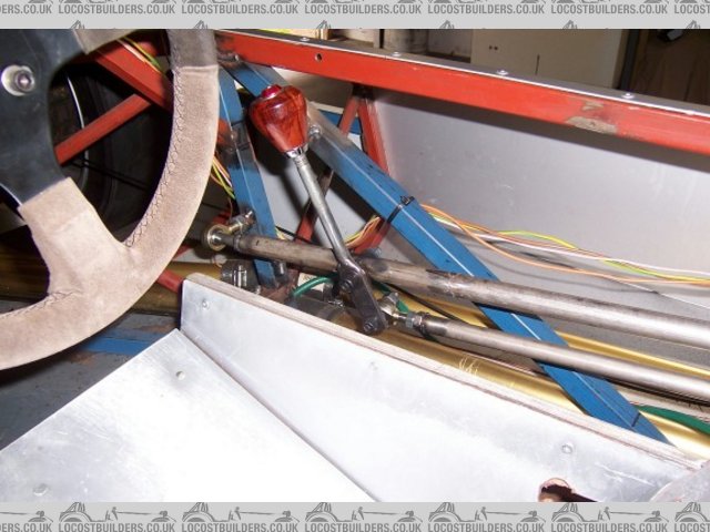
Andy - Thanks a lot for the E mail with photos you sent me. I have now reworked the gearshift lever along the lines of that example, which corrects
the fore and aft movement, which I had wrong (as also pointed out by Russ). That linkage has the advantage that the lever ratio of the fore/aft moment
and left/right movement can easily be adjusted independently.
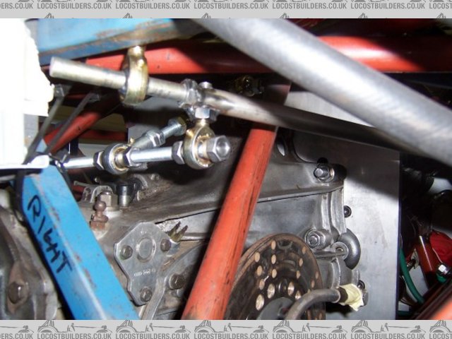
This change, along with an improved linkage at the gearbox end, and some fiddling with the various lever lengths has improved the shift action
dramatically.
The very rough and ready experimental parts shown will be replace with properly machined and fabricated components when I do the final chassis build
up.
Cheers
Fred W B
lever 2
links rear
[Edited on 29/12/05 by Fred W B]
|
|
|