Mark Allanson
|
| posted on 2/3/03 at 05:35 PM |

|
|
Plenum chamber height reduction
Has anyone tried the Hoodie developed mod for the EFi plenum chamber? The guy who has done it wants £25 for the instructions and 4 blanking plates, he
says that no welding is required, so I guess that the thing is glued back together?
In any event, I am going the chop mine down - I just want a head start on any difficulties others have come across when doing this
Mark
Rescued attachment 250401-EFi4.jpg
|
|
|
|
|
chrisg
|
| posted on 2/3/03 at 07:37 PM |
|
|
I'd be interested in this as I intend to put the EFi eventually, is that a picture of it lowered Mark?
Cheers
Chris
Note to all: I really don't know when to leave well alone. I tried to get clever with the mods, then when they gave me a lifeline to see the
error of my ways, I tried to incite more trouble via u2u. So now I'm banned, never to return again. They should have done it years ago!
|
|
|
Mark Allanson
|
| posted on 2/3/03 at 08:29 PM |
|
|
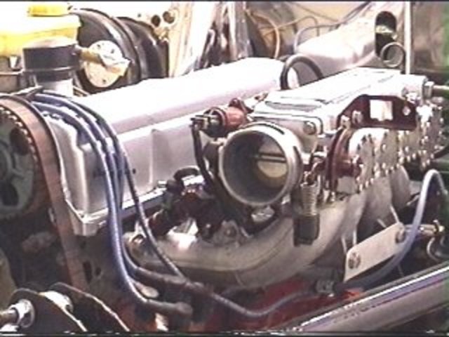
It's a shot of one done in a 2B, the plenum is cut off about half way and where it enters the throttle chamber, then joined again under the throttle
chamber - the details I have yet to find out!
Rescued attachment efi_1.jpg
|
|
|
fastenuff
|
| posted on 2/3/03 at 08:43 PM |
|
|
hmm no welding ..............? possible I reckon.
You could try and get some info of the belgium tiger importer. they do something simular. They bought my engine some time ago.
Ingmar
|
|
|
Mark Allanson
|
| posted on 3/3/03 at 07:54 AM |
|
|
Any site address?
|
|
|
CairB
|
| posted on 3/3/03 at 01:06 PM |
|
|
Mark,
I've done it on a 2.0 pinto in an Indy. I bought the kit to get an idea but I wasn't confident that it would fit - it didn't - I had to be more
aggresive with the reduction. Photos in Cairb - Under bonnet. Theres a steel plate that fits between the 2 cut sections with screws passing through
into the ally from both sides. No welding ... apart from a bit of filling to give a bit more meat for the screws. It seems to drive well enough.
|
|
|
Mark Allanson
|
| posted on 3/3/03 at 09:19 PM |
|
|
Did you need to cut it down further for the height or the width? I hadn't considered turning the throttle chamber the other way around, what are the
advantages/disadvantages?
Mark
|
|
|
CairB
|
| posted on 3/3/03 at 09:47 PM |
|
|
It was all a bit tight width and height wise. turning it round seemed to give a better chance at mating up the cut down tubes to the underside of the
plenum chamber. Disadvantage at the moment is the ducting of cool air for the inlet, but its currently pulling sub 6s 0-60 so its probably not too
detrimental, or is there more grunt available  . .
The kit was useful for seeing how it had been done but I think that there's a tad more room under the Hoods hood. I only used a small part of the kit
in the end.
There was a web site where someone fabricated a new plenum and fitted pressed tubes into the cut down section close to the injectors.
I found that once I'd started cutting the unit it became a challenge, it was a bit of a job but hopefully in the locost spirit.
I'm currently looking into fitting a wide band O2 sensor to get a handle on whether there's any gain to be had by modifying the injection, has
anyone any experience?
|
|
|
Northy
|
| posted on 3/3/03 at 09:54 PM |
|
|
I'm looking into doing this on my Vx Inlet maqnifold. What are the principles? I'm guessing airflow must not be restricted etc.
I'd like as much info as poss please.
There is a local company who could weld it for me.
Thanks
Graham
Website under construction. Help greatfully received as I don't really know what I'm doing! 
"If a man says something in the woods and there are no women there, is he still wrong?"
Built 2L 8 Valve Vx Powered Avon
|
|
|
CairB
|
| posted on 3/3/03 at 10:10 PM |
|
|
Northy,
I'm not sure how it would work on yours. Cutting mine back further makes the rear inlet come into the plenum at a slight angle and due to the
thickness of the plenum there was only a limited amount of radiusing that could be done at the inlet entry. Both of these are going to reduce the
flow. Also the inlet length is reduced which will push up the rev range the point at which resonance will occur, loose some bottom - gain some top.
However, I worked on the basis of suck it and see, or was it blow it?
It if doesn't work the main cost is time, oh and then the throttle bodies etc
|
|
|
Northy
|
| posted on 3/3/03 at 10:28 PM |
|
|
CairB,
Were the bits you cut out quite straight? The ones on the VX curve a bit.
What do you mean by pushing up the rev range the point at which resonance will occcur? You lost me there!
Loose some bottom - gain some top?
Thanks
Graham
Website under construction. Help greatfully received as I don't really know what I'm doing!
"If a man says something in the woods and there are no women there, is he still wrong?"
Built 2L 8 Valve Vx Powered Avon
|
|
|
CairB
|
| posted on 4/3/03 at 12:53 PM |
|
|
Northy,
I think that if you look at the photo Cairb - Under bonnet side view, and Marks picture earlier on in this thread you will get some idea of the shape
of the cut out section. It was tricky as the pipes curve a lot for the rear cylinder, which is the one that connects at a slight angle. The kit is
based on the picture that Mark showed where the pipes were still round in cross section. Mine deviate somwhat from this, but it doesn't seem to
affect performance significantly.
When the inlet manifold length is reduced then the pressure waves that bounce between the changes in cross sectional area of the duct will increase in
frequency, hence the useful effect of getting extra charge in the cylinder will occur higher up the rev range, all else being the same. I believe that
the original length of the inlet manifold was to give boost at the lower RPM range. How significant this effect is on a 'cooking' engine is
debatable. Hence the term lose some bottom - gain some top. I think that there was a reference to a University students thesis on the subject recently
- sorry can't remeber the link.
I hope this clarifies.
Cheers
|
|
|
rgv_stu
|
| posted on 4/3/03 at 04:23 PM |
|
|
northy are you avonbuilder on mig??
is the vaux lump a 16 or 8v?
i would say that shortening the runners is a bad idea as they are a tuned length to the plenum.
this can throw the afm out iirc as pulses coming back up the inlet confuses the afm. this is supposed to be worse with a performance cam.dont know how
the form system works but i presume its similar
imo if access is a problem i would have thought a set of webers would be a better idea than hacking the injection around.
|
|
|
Northy
|
| posted on 4/3/03 at 05:57 PM |
|
|
Thanks,
Yeah thats me. It is an 8 Valve. Fitting carbs doesn't seem straight forward either
Don't know what to do now
Graham
Website under construction. Help greatfully received as I don't really know what I'm doing!
"If a man says something in the woods and there are no women there, is he still wrong?"
Built 2L 8 Valve Vx Powered Avon
|
|
|
Mark Allanson
|
| posted on 4/3/03 at 09:10 PM |
|
|
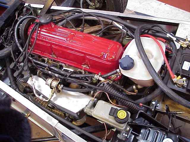
I researching this a bit, everyone seems to have done it differently, just found another interesting one, it may be a bit more involved
though
Rescued attachment Radical Mod EFI2.jpg
|
|
|
Northy
|
| posted on 4/3/03 at 09:20 PM |
|
|
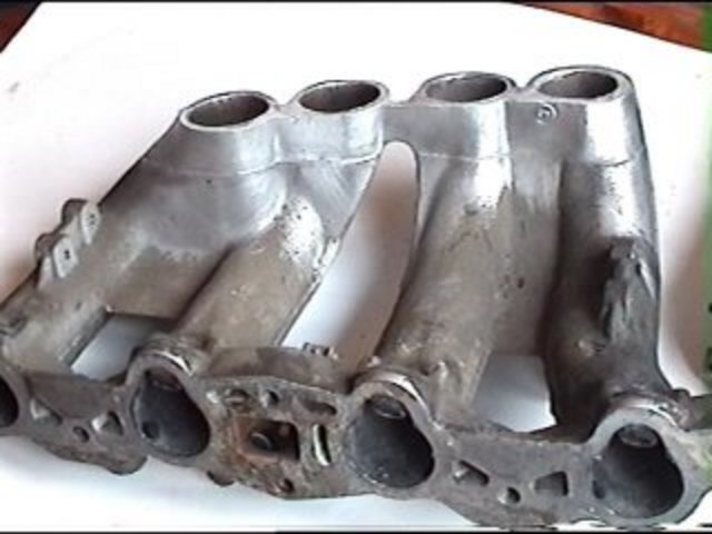
Have you seen this one?
Rescued attachment Moded Inlet Manifold Cat.jpg
Graham
Website under construction. Help greatfully received as I don't really know what I'm doing!
"If a man says something in the woods and there are no women there, is he still wrong?"
Built 2L 8 Valve Vx Powered Avon
|
|
|
Northy
|
| posted on 4/3/03 at 09:41 PM |
|
|
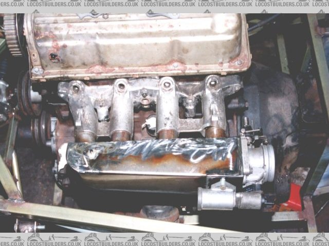
This is what I am trying to modify
 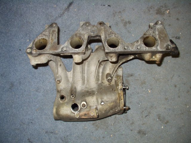
Rescued attachment EFi Manifold Standard.jpg
Graham
Website under construction. Help greatfully received as I don't really know what I'm doing!
"If a man says something in the woods and there are no women there, is he still wrong?"
Built 2L 8 Valve Vx Powered Avon
|
|
|
Mark Allanson
|
| posted on 4/3/03 at 10:00 PM |
|
|
That is one seriously awkward shape!!
Best of luck
|
|
|
CairB
|
| posted on 4/3/03 at 10:22 PM |
|
|
I'll second that - I thought the pinto was tricky. It looks like you would end up with some awkward tube intersection angles depending on how much
needs to be removed. Have you come across anyone else that has modified this type?
Mark,
Your previous picture was the one that I was refering to with the pressed in tubes. It's probably not too bad once the manifold has been bored out as
long as its welded in a particular sequence and gives the opportunity to get the plenum end of the inlet pipes with adecent entry radius. Have you
decided which way to go yet?
Cheers,
Colin
|
|
|
chrisg
|
| posted on 4/3/03 at 10:41 PM |
|
|
Colin,
I know it's changing the subject slightly, but what was the wiring like, that's the bit that's worrying me! Do you have a wiring diagram?
cheers
Chris
Note to all: I really don't know when to leave well alone. I tried to get clever with the mods, then when they gave me a lifeline to see the
error of my ways, I tried to incite more trouble via u2u. So now I'm banned, never to return again. They should have done it years ago!
|
|
|
Mark Allanson
|
| posted on 4/3/03 at 10:45 PM |
|
|
I quite like the idea of making my own plenum chamber, not even I can weld mild steel to aluminium so I am going to check out the heat resistance of
the structural adhesives we use at work.
I was thinking about making the outer part of the modified inlets into trumpets to increase the efficiency, would this work even though they are
inside the plenum chamber?
I have got a copy of the piper tuning manual somewhere, it has all kinds of maths for working out lengths of inlets and exhausts to give maximum power
at prefered RPM's - just cannot find it at the moment!
|
|
|
CairB
|
| posted on 4/3/03 at 10:54 PM |
|
|
Chris,
Sent a U2U2U
Mark,
I think that radiusing the inlet entry would help in the plenum as long as they don't protrude into the chamber significantly. What it's trying to
do is to get the air into the tube witout the sideways flow becoming significant and reducing the effective area.
As for the tubes I would have thought that the inlet temperature rise would be less than 80C which should give scope for a slight interference not
coming loose, the adhesive could be used to help seal, if the ally is heated then you would get the tubes in without wiping away all the adhesive.
[Edited on 4/3/03 by CairB]
|
|
|
Northy
|
| posted on 5/3/03 at 07:38 AM |
|
|
Can someone post a picture of the Pinto Inlet so I can see the difference? It might help me work out how to do it.
Thanks
Graham
Website under construction. Help greatfully received as I don't really know what I'm doing!
"If a man says something in the woods and there are no women there, is he still wrong?"
Built 2L 8 Valve Vx Powered Avon
|
|
|
rgv_stu
|
| posted on 5/3/03 at 01:40 PM |
|
|
whats the problem with webers northy ??
is that 8v with single throttle opening or twin ??
the runners are long which helps with mid/low torque.
put a post on mig about modifying the plenum and see what they say but i think you will find that they will say to keep the runners the same length.
|
|
|
CairB
|
| posted on 5/3/03 at 06:15 PM |
|
|
Northy,
I've posted a photo in Cairb - Pinto Plenum before modification for your perusal.
Cheers,
Colin
|
|
|


