waterrat
|
| posted on 21/2/07 at 09:27 PM |

|
|
double wishbone geometry
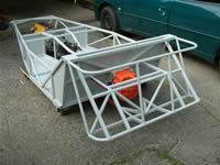
i'm working on the final stages of construction of the frame for my build. it's wider than normal locosts and i'm tring to redesign
the locost double wishbone suspention to work with my project. i was hoping that someone would let me know if there is a special formular for
suspention.
|
|
|
|
|
SeaBass
|
| posted on 21/2/07 at 09:36 PM |
|
|
See Race and Rally Sourcebook by Alan Staniforth. I saw a copy at Halfrauds in the sale the other day.
Cheers
|
|
|
zetec7
|
| posted on 21/2/07 at 09:41 PM |
|
|
Wow, tough question...basically, the answer is no, there's no formula (there's almost no two cars alike in the true Locosts, so no one
formula could apply). It's going to depend on what spindles you are using & how wide the rear end of the car is (the rear track, that
is...). I recommend starting at the back and working forward. Once you have the rear end, you can figure out how wide the front needs to be, so you
can start to figure out how long your a-arms need to be, etc. And, you can measure off the rear end for reference. You need to have SOMETHING you
can measure from to get it all right.
We didn't use a formula for our +2 frames - we finished our rear suspension, then propped our spindles up where they needed to be for the width
to be right. Then we designed our a-arms to suit, and it all worked beautifully. 
http://www.freewebs.com/zetec7/
|
|
|
ProjectX
|
| posted on 21/2/07 at 09:43 PM |
|
|
Hi
Buy this
http://www.amazon.co.uk/gp/product/1903706734/ref=sib_rdr_dp/202-4129879-0675017
Read it and enjoy
HTH
J
[Edited on 21/2/07 by ProjectX]
|
|
|
nitram38
|
| posted on 21/2/07 at 09:44 PM |
|
|
There is a rough guide that the top wishbone is 70-80% of the length of the bottom one.
It is not an exact science as it depends on what your car is used for.
Unequal wishbones usually increase negative camber when in droop and positive when they are up, which is useful in corners to keep the tyre tread in
contact with the road.
Too much camber change will have the opposite effect, so you can go to far.
See the end of my thread here. The suspension I designed is for air suspension
with compressor ride height adjustment.
In order to save the tyres, my camber hardly changes when I pump the suspension up 3" higher than my normal ride height.
Yours will need to introduce some camber, but this will also depend on the maximum travel of your wishbones.
It is not easy !!!!!!!!!!!!
[Edited on 21/2/2007 by nitram38]
|
|
|
craig1410
|
| posted on 21/2/07 at 09:59 PM |
|
|
quote:
Originally posted by nitram38
Unequal wishbones usually increase negative camber when in droop and positive when they are up, which is useful in corners to keep the tyre tread in
contact with the road.
Didn't you mean the other way around? When in droop you want some positive camber and in compression you want more negative camber. Negative
camber is where the top of the tyre is closer to the vehicle centreline than the bottom of the tyre.
Cheers,
Craig.
|
|
|
stig mills
|
| posted on 21/2/07 at 10:02 PM |
|
|
Which kit car mag have a feature this month that touches on the subject of suspension/steering geometry for my car the MEV ROCKET. It is not a full
guide but does outline the basic priciples apart from scrub radius and roll centres. You could do alot worse than making a model from 25x3mm stock and
experiment to discover the effects of the ackerman principle or the importance of the rack location. Have fun, regards Stig Mills
|
|
|
nitram38
|
| posted on 21/2/07 at 10:09 PM |
|
|
quote:
Originally posted by craig1410
quote:
Originally posted by nitram38
Unequal wishbones usually increase negative camber when in droop and positive when they are up, which is useful in corners to keep the tyre tread in
contact with the road.
Didn't you mean the other way around? When in droop you want some positive camber and in compression you want more negative camber. Negative
camber is where the top of the tyre is closer to the vehicle centreline than the bottom of the tyre.
Cheers,
Craig.
Here is exagerated droop (my suspension will never go this far !) and it clearly shows negative. I made a mistake though, in bounce it goes negative
too!
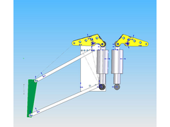 
camber change
camber change up
[Edited on 21/2/2007 by nitram38]
[Edited on 21/2/2007 by nitram38]
|
|
|
nitram38
|
| posted on 21/2/07 at 10:25 PM |
|
|
unequal wishbones
equal
|
|
|
Andy S
|
| posted on 21/2/07 at 10:45 PM |
|
|
The reason your design does not follow the convention of positive in droop and negative in bounce is that your wishbones are almost parallel.
The recognised starting point is top bone 2/3 length of lower - the lower rising to chassis at 10 degress at rest and the upper bone at an angle of
20-25 degrees falling toward the chassis.
Parallel bones give lousy camber control in roll.
Pivot your design around the roill centre at you design suspension movement and see what happens.
Andrew
oops - beaten to it
|
|
|
lotustwincam
|
| posted on 21/2/07 at 10:59 PM |
|
|
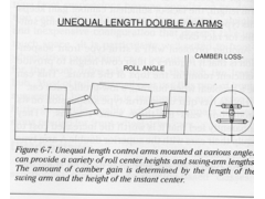
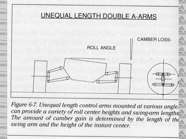
Fig. 6.7 clearly shows that in relation to the body, suspension goes positive camber on droop, and negative camber on compression.
If it were to go positive on compression, the whole objective of un-equal length, non parallel wishbones would be lost.
[Edited on 21/2/07 by lotustwincam]
|
|
|
ProjectX
|
| posted on 21/2/07 at 11:09 PM |
|
|
Wow! Fig 6.7!! WTF
Look at both drawings. One chassis has straight sides the other angled. So both designs are flawed!
Unequal wisbone length only works if the measurement is from the same starting point. ie in our case the chassis. Im going to draw a pic and post
after this one
J
|
|
|
nitram38
|
| posted on 21/2/07 at 11:10 PM |
|
|
quote:
Originally posted by Andy S
The reason your design does not follow the convention of positive in droop and negative in bounce is that your wishbones are almost parallel.
The recognised starting point is top bone 2/3 length of lower - the lower rising to chassis at 10 degress at rest and the upper bone at an angle of
20-25 degrees falling toward the chassis.
Parallel bones give lousy camber control in roll.
Pivot your design around the roill centre at you design suspension movement and see what happens.
Andrew
oops - beaten to it
I deliberately did this as I need to pump up the suspension by 3" at times without too much camber gain.
I aim to run quite stiff suspension so my wishbones will only move around 20mm in each direction.
With my model I do get some camber change but it is minimal.
I have made some rod end adjusters that will enable me to quickly and acurately adjust them, should I want to track the car. At that time I can dial
in more negative camber.
The adjusters will allow me to move the rod end in or out without removing the wheel from the hub and will give me infinite increments of adjustment.
Usually all you can get is 180 degress adjustment.
Here is a picture. It should show a tread on the adjuster. The silver part will be part of the wishbone.
[img][/img]
|
|
|
nitram38
|
| posted on 21/2/07 at 11:18 PM |
|
|
quote:
Originally posted by ProjectX
Wow! Fig 6.7!! WTF
Look at both drawings. One chassis has straight sides the other angled. So both designs are flawed!
Unequal wisbone length only works if the measurement is from the same starting point. ie in our case the chassis. Im going to draw a pic and post
after this one
J
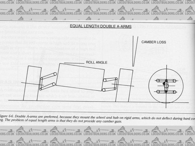
Look again, one is an Equal wishbone set up.
|
|
|
ProjectX
|
| posted on 21/2/07 at 11:30 PM |
|
|
Look again, one is an Equal wishbone set up.
Yes but equal on straight sided chassis and unequal on angled chassis. You need to think about the moment of movement not what it relates to! Also
think of KPI as this will also affect the angles.
I do like your air idea thou, let me know how you get on.
Cheers J
|
|
|
craig1410
|
| posted on 22/2/07 at 12:25 AM |
|
|
Nitram,
Don't take this the wrong way but I'm not sure your design is what most people would want. Not many of us require to be able to
"pump up" the suspension by 3" and still have workable camber - I would have thought that most of us would want optimal camber
control through the normal working range. Fine if you need to pump up the height to clear speed bumps on your way to the track but I would happily
accept a couple of degrees of positive camber while a slowly drove over the bumps and then put it back to normal once clear.
Usually you would want a bit of static negative camber with negative gain on compression and ideally a bit of positive camber on maximum droop. This
will allow the tyres to maintain a good position relative to the road to yield maximum grip. I have the Staniforth book on suspension design by the
way and have read it a number of times although I don't claim to be an expert on IRS design. I went the de-dion route myself but that's a
different story...
I think if someone wants "general" advice on IRS double wishbone geometry then in my opinion they should look at some of the general
guidelines quoted above rather than any one, perhaps specialised, design.
Cheers,
Craig.
|
|
|
nitram38
|
| posted on 22/2/07 at 04:22 AM |
|
|
I wasn't trying to get my design across it was just that I only had those diagrams on my hardrive 
I then went and got a book and scanned it.
The straight sided versus angled side drawings are just a couple of diagrams to demonstrate the differences between equal and unequal setups.
I think the auther was just trying to show in a simple form that each set of wishbones were different lengths.
There will be static camber, it is just a solidworks mock up to find out the limits I need.
There is camber gain in my car set up, it is just not as much as you are used to, but then again my suspension is trying to acheive the best of two
options and in the end there has to be compromise.
[Edited on 22/2/2007 by nitram38]
|
|
|
britishtrident
|
| posted on 22/2/07 at 07:29 AM |
|
|
quote:
Originally posted by Andy S
The reason your design does not follow the convention of positive in droop and negative in bounce is that your wishbones are almost parallel.
The recognised starting point is top bone 2/3 length of lower - the lower rising to chassis at 10 degress at rest and the upper bone at an angle of
20-25 degrees falling toward the chassis.
Parallel bones give lousy camber control in roll.
Pivot your design around the roill centre at you design suspension movement and see what happens.
Andrew
oops - beaten to it
Nicely put Right on the button near equal length top and bottom wishbones are only on F1 style cars which have virtually zero roll because the
suspension stiffness is several tons per inch.
|
|
|
nitram38
|
| posted on 22/2/07 at 12:21 PM |
|
|
Take a look at my car in my archive.
It has parrallel wishbones and goes around corners like they are not there!
My spring rates are about 100lbs higher than the locost ones.
If you read any suspension books, unequal bones are often exagerated in diagrams to demonstrate a point.
As I said, in the working range of my bones, they will work fine.
I don't get loads of body roll in my current car and I don't expect lots in the new one either
Saying all that I will try the tilted bones option tonight on solidworks and see if there will be any benefits to my design.
[Edited on 22/2/2007 by nitram38]
|
|
|
bartonp
|
| posted on 22/2/07 at 12:25 PM |
|
|
Exactly - camber change induced by unequal lengths is dialled-in to try to allow the wheel to remain upright in cornering and offer a full contact
patch only where this would not be the case due to body roll.... if there's no roll then there's no need for much camber change either!
|
|
|
britishtrident
|
| posted on 22/2/07 at 12:50 PM |
|
|
On any normal car ie anything outside of F1 car which have to cope with many tons of aerodynamic download, the only reason to grossly stiffen the
suspension is if either the something in suspension geometry is very amiss or the chassis is so flexible that oversterr/understeer balance won't
respond to reasonable changes in roll stiffness on one axle.
If the suspension is made too hard either in bump or in roll the tyres can't keep contact with the road. All will feel great up untill the
point where an outside tyre suddenly looses contact with the road, usually resulting in a very sudden spin in to the barrier..
The norm since the 1930s for double wishbone suspension is the top wishbone should be be 2/3 to 3/4 the length of the lower wishbone, the illustration
in books aren't exagerated, many top wishbones on production cars are actually much shorter than this rule of thumb.
For a wider than normal chassis the book Cortina or other Sierra style wishbone should be be fine provided the inner pivots on each side are in the
same postional relationship to each other.
[Edited on 22/2/07 by britishtrident]
|
|
|
kb58
|
| posted on 22/2/07 at 02:25 PM |
|
|
quote:
Originally posted by britishtrident
...the only reason to grossly stiffen the suspension is ... that the chassis is so flexible that oversterr/understeer balance won't respond to
reasonable changes in roll stiffness on one axle.
[Edited on 22/2/07 by britishtrident]
Mmmm, no. If the chassis is flexible, stiffening the springs will not make any difference - the chassis will just flex more. Same thing with
stiffening the shocks or anti-roll bars. This is why it's so important to have a stiff chassis to begin with, it provides the ability to tune
handling.
[Edited on 2/22/07 by kb58]
Mid-engine Locost - http://www.midlana.com
And the book - http://www.lulu.com/shop/kurt-bilinski/midlana/paperback/product-21330662.html
Kimini - a tube-frame, carbon shell, Honda Prelude VTEC mid-engine Mini: http://www.kimini.com
And its book -
http://www.lulu.com/shop/kurt-bilinski/kimini-how-to-design-and-build-a-mid-engine-sports-car-from-scratch/paperback/product-4858803.html
|
|
|
nitram38
|
| posted on 22/2/07 at 07:01 PM |
|
|
quote:
Originally posted by Andy S
The reason your design does not follow the convention of positive in droop and negative in bounce is that your wishbones are almost parallel.
The recognised starting point is top bone 2/3 length of lower - the lower rising to chassis at 10 degress at rest and the upper bone at an angle of
20-25 degrees falling toward the chassis.
Parallel bones give lousy camber control in roll.
Pivot your design around the roill centre at you design suspension movement and see what happens.
Andrew
oops - beaten to it
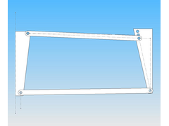
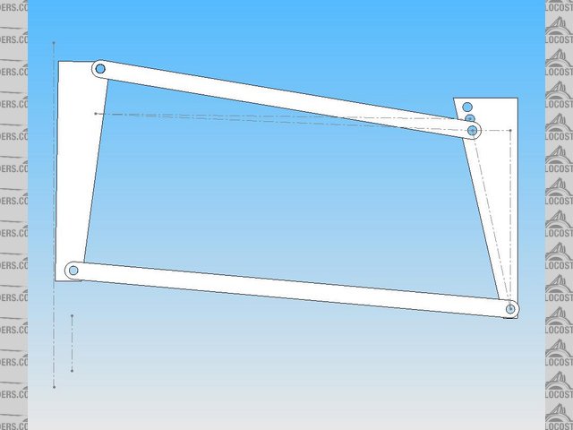
I adjusted the wishbones by the degrees you suggested. Where did you take the 10 and 20 degrees from?
[img][/img]
|
|
|
nitram38
|
| posted on 22/2/07 at 09:11 PM |
|
|
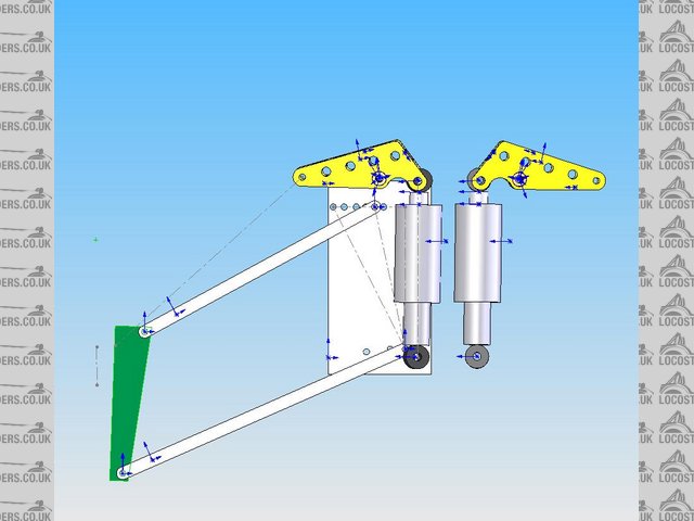
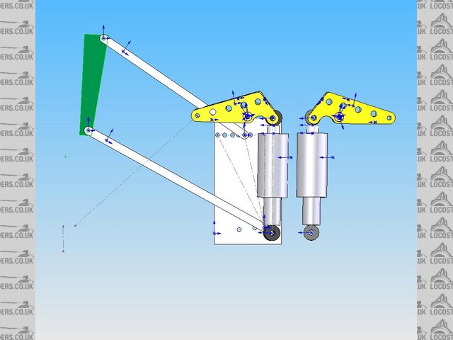
I have listened and adjusted my suspension. Now I will get camber change when I raise the car up the extra 3".
At ride height:
 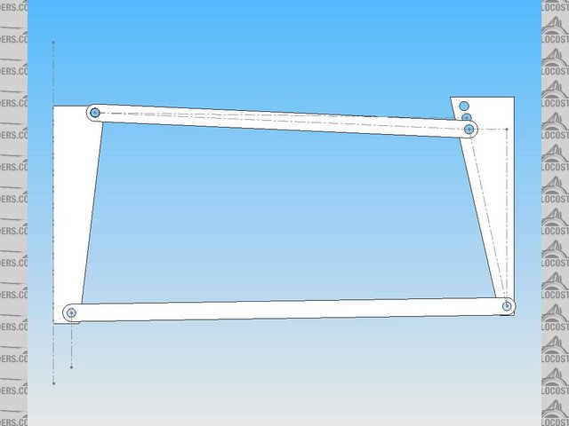
Description
At highest setting with extra 3" of ride height:
 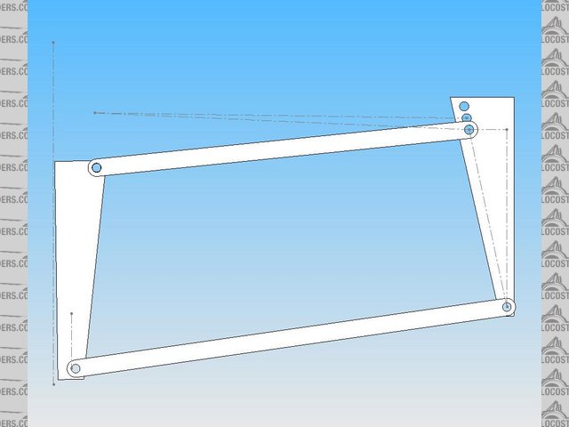
centred suspension
At full bounce wishbone setting:
up
[Edited on 22/2/2007 by nitram38]
|
|
|
JoelP
|
| posted on 22/2/07 at 09:22 PM |
|
|
nitram, have you considered having two different mounting points for the wishbones? The, for temporary raises you could just up the air and put up
with any camber change, or for more longer term high rides (ie to a show for a weekend etc) you could reattach the bones lower on the car. Just an
idea.
|
|
|