Fred W B
|
| posted on 31/3/08 at 02:40 PM |

|
|
Modified cortina upright geometry for CANAMSA
On the mechanical side (for a change) I have started working out what machined bits I need to get made up to attach the top M16 rod end and the lower
bearing to the cortina front uprights.
At the moment I have 225/60 tyres on 7 supalights with offset of 12P and back space of 112mm. This gives a large scrub radius with the standard
cortina uprights.
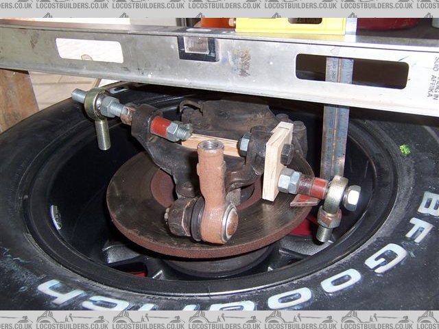
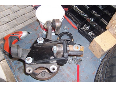
If I move the lower joint outwards as shown in the photo I can get a KPI of 12 10 degrees, with a scrub radius of 18 to 38 mm respectively. I could
do this by making up a bracket like this wooden mock up. I was thinking 12 mm steel for the lower offset plate, with a stepped lower stud tapped,
screwed and then puddle welded to the plate on the back side.
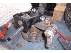
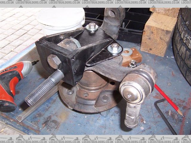
The flat plate is bolted to the body of the upright through the existing M8 tapped holes in the upright, with spacers below welded to the plate. This
plate maybe 6 mm, and the webs in 8 mm? The vertical load would be taken by the 12mm plate, with the webs providing fore and aft stability.
I want to be able to eventually upgrade to custom 8J rims, with offset such that the outer rim face sits in the same place as now. This would reduce
the scrub radius by a further 12 mm.
I may eventually end up getting uprights cast, so consider this a development prototype.
Thoughts anybody?
Cheers
Fred W B
upright geo mock
upright bracket 1
 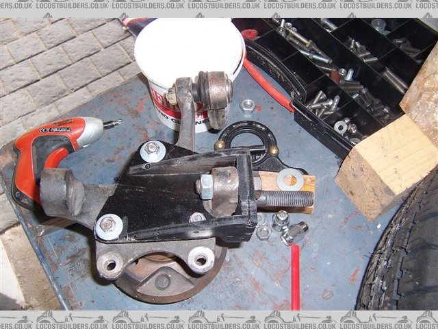
upright bracket 2
[Edited on 31/3/08 by Fred W B]
[Edited on 31/3/08 by Fred W B]
You can do it quickly. You can do it cheap. You can do it right. Pick any two.
|
|
|
|
|
JAG
|
| posted on 31/3/08 at 03:07 PM |
|
|
I cannot comment on the geometry mods that you're proposing except to say that I have read that the standard Cortina geometry is not ideal.
However you're proposed method for modifiying the standard Cortina upright certainly looks solid enough. Obviously without any simulation
software (ANSYS FEA etc...) you just have to rely on physical testing.
I think I would definitely make a pair for real and give it a go - keep us uptodate on your success as I can imagine quite a few people would be
interested in making their own if they work - and you're happy with that of course 
Edited to add that you could also incorporate the cycle wing bracket into them.
[Edited on 31/3/08 by JAG]
Justin
Who is this super hero? Sarge? ...No.
Rosemary, the telephone operator? ...No.
Penry, the mild-mannered janitor? ...Could be!
|
|
|
Mr Whippy
|
| posted on 31/3/08 at 03:26 PM |
|
|
my first reaction is, why are they so heavy? my indi's rear fabricated uprights were made from less than 3mm sheet. I've looked closely at
fabricated uprights on a rather well made old formula car and the uprights although quite large, I discovered by tapping them, are in fact thin walled
hollow boxes (expertly made) they must have weighed next to nothing but looked very strong.
[Edited on 31/3/08 by Mr Whippy]
|
|
|
MikeR
|
| posted on 31/3/08 at 05:56 PM |
|
|
have you looked at the wilwood caliper?
I've no idea what its dimensions are, but it may be better / lighter (although more expensive).
good luck.
|
|
|
ecosse
|
| posted on 31/3/08 at 06:43 PM |
|
|
Ingenious way to do it for sure 
But while I'm not able to comment on the geometry, I get the feeling that you are not be far away from actually constructing a complete upright
from scratch anyway i.e. fabricate another mount on the top and add a steering arm (okay I simplified that a touch  ) and add a stub pin, which would
be a lot lighter than fabricating around the tina parts, and would get you the exact geometry required? ) and add a stub pin, which would
be a lot lighter than fabricating around the tina parts, and would get you the exact geometry required?
Cheers
Alex
|
|
|
Fred W B
|
| posted on 1/4/08 at 03:35 PM |
|
|
Thanks for responses so far guys.
So where are all the resident experts? What with my proposal containing possibly wacky ideas relating to various "hot button" items such
as:
welding up upright bits
rod end use as pivots
ackermann
front geometry
I was expecting more comment, considering how recent similar posts have been responded to
Cheers
Fred W B
You can do it quickly. You can do it cheap. You can do it right. Pick any two.
|
|
|