Alan B
|
| posted on 3/6/08 at 01:10 AM |

|
|
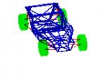
And now the rear end...


|
|
|
|
|
Sven
|
| posted on 3/6/08 at 02:39 AM |
|
|
Beautifully done, Alan!
"Lightheadedness through quickness"
|
|
|
TheGecko
|
| posted on 3/6/08 at 03:17 AM |
|
|
Very nice work Alan, as always. I particularly like the criss-cross bottom wishbone - should be light but stiff.
Must be close to drivable now?
Dominic
|
|
|
worX
|
| posted on 3/6/08 at 09:07 AM |
|
|
Very nice.
Have you seen the pattern for the lower rear wishbone on something else or did you come up with that yourself Alan?
Steve

|
|
|
nick205
|
| posted on 3/6/08 at 09:11 AM |
|
|
to your usual standardas Alan - beautiful 
|
|
|
Alan B
|
| posted on 3/6/08 at 12:00 PM |
|
|
Thanks guys..positive encouragement is always welcome.. ....as is critisism too.. ....as is critisism too..
To be honest, I'm not sure if I'd seen the criss-cross lower wishbone before or not, but it works in this application because the toe
adjustment is right at the outer rod ends rather than a seperate link. It does, however, rely on accurate spacing between rod ends so that they
aren't unduly stressed when tightened. Of course any toe change will affect the distance between crush surfaces on the upright, but it's
very small...1.5 degrees of toe change makes only 0.002" of difference. Again, thanks..it is very much appreciated.
|
|
|
eccsmk
|
| posted on 3/6/08 at 12:25 PM |
|
|
quote:
Originally posted by Alan B
Thanks guys..positive encouragement is always welcome......as is critisism too..
thats rubbish lol
only joking top job there you should be really proud of that well done !
|
|
|
mookaloid
|
| posted on 3/6/08 at 01:22 PM |
|
|
I'm really liking the way this car is shaping up
Well done that man - keep up the good work!
Cheers
Mark
"That thing you're thinking - it wont be that."

|
|
|
skydivepaul
|
| posted on 4/6/08 at 02:07 AM |
|
|
looking very nice Alan.
Has the paint dried yet
http://www.smartideasuk.com
http://www.smartmapping.co.uk
HD CCTV
3D design solutions and integration
IP security systems
access control systems
|
|
|
Alan B
|
| posted on 4/6/08 at 02:14 AM |
|
|
quote:
Originally posted by skydivepaul
looking very nice Alan.
Has the paint dried yet
Has it bollocks...unbelievable in these temperatures....
Good job I'm planning a stripdown, grit blast and re-paint after it's built and tested...
|
|
|
Spyderman
|
| posted on 4/6/08 at 01:23 PM |
|
|
It looks very nice Alan. Very tidy indeed.
The one thing I would be worried about is the welded joint between the wishbones and the rod ends at the chassis end due to the extreme angle. What I
am thinking of is when the side loading is high during cornering, any shock loading is putting a lot of stress, as leverage into the welded joint.
I certainly wouldn't criticise your welding as I am no expert, but am merely voicing my fears!
I say this because in normal wishbones the loading is going in a straight line from the wishbone into the pivot so that any welded joint is only in
tension or compression. With your joints there is a bending force also. Due to the very wide angle of the wishbones they need to be more resistant to
bending loads than in a normal situation, hence the greater loading on the pivots and welds.
Tell me to shut up if I am talking b0ll0cks!
Spyderman
|
|
|
Alan B
|
| posted on 4/6/08 at 02:04 PM |
|
|
Terry, your observations are accurate and in particular on the top wishbone, that is why I'll be be putting a tube lengthways between the rod
end tube joints (also spotted by Syd, so you are in good company)...the tube should arrive today.
It's really not as bad it looks from the pics, but for the sake of a small tube to triangulate the wishbone it's silly not to.
Thanks all for the comments.
Alan
|
|
|
JC
|
| posted on 5/6/08 at 11:10 AM |
|
|
Alan, quick question - what size are the bolts that mount the rear calipers to your uprights? I'm looking to use the same and am want to check
before I buy!!!
Fab build - keep it up!
JC
|
|
|
Alan B
|
| posted on 5/6/08 at 11:26 AM |
|
|
Thanks JC...
The bolts I'm using are high tensile M10 x 1.25 x 40 long...your length could vary as I'm bolting through a 1/2" (13mm) flange.
HTH,
Alan
|
|
|
JC
|
| posted on 5/6/08 at 07:42 PM |
|
|
Thanks Alan, that's perfect!
|
|
|