novacaine
|
| posted on 26/8/08 at 09:15 PM |

|
|
Haynes roadster brake pedal design analysis
after a bit of a play on solidworks to analyse the brake pedal as detailed in the "book" i have come up with some interesting results
 
old profile results
this is the pedal assembly as detailed in the book, with 150 kg force applied to it
see this thread
The red area around the front face of the pedal (with the black arrow) is showing an area of concentrated stress
from what i can tell that "bend" is unnececary and weakens the pedal,
this is the results of the test if that "bend" is ommitted and a straight line is drawn between the pad of the pedal and the bump stop
 
results of new profile
this is the edited profile of the brake pedal (see the book for the original)
 
edited profile of brake pedal
can anyone see why such a modification couldnt be carried out? i cant imagine that they put that dip in for no reason, maybe for comfort? and
ideas?
matt
And you run and you run to catch up with the sun but its sinking, Racing around to come up behind you again, the sun is the same in a relative way but
your older, shorter of breath and one day closer to death
|
|
|
|
|
chrisg
|
| posted on 26/8/08 at 09:37 PM |
|
|
There's no reason not to omit the bend.
It does give a little more room for the larger foot, but even the prototype has a constant curve from top to bottom.
It's interesting to see that analysis and compare it with the one I did which used a 300kg force as an ultimate test, which showed a buckling
failure along the length of the pedal.
I once came upon a tractor round a country bend and stood on the middle pedal so hard that I banged my head on the roll bar, but it's still
fine. I suppose it's all relative, and the good thing is that using FEA you can take parts to destruction and beyond without risk.
Now the serious bit.
You need a holiday, get out for a walk or go for a pint - Anyone who does stress analysis for "fun" has serious problems!
Cheers
Chris
Note to all: I really don't know when to leave well alone. I tried to get clever with the mods, then when they gave me a lifeline to see the
error of my ways, I tried to incite more trouble via u2u. So now I'm banned, never to return again. They should have done it years ago!
|
|
|
caber
|
| posted on 26/8/08 at 09:47 PM |
|
|
" I banged my head on the roll bar, but it's still fine"
head or rollbar? how's the pedal
Caber
|
|
|
Paul TigerB6
|
| posted on 26/8/08 at 09:50 PM |
|
|
quote:
Originally posted by chrisgI once came upon a tractor round a country bend and stood on the middle pedal so hard that I banged my head
on the roll bar, but it's still fine.
Glad to hear your roll bar didnt get dented when it contacted your head Chris.....
Damn - too slow again!! 
[Edited on 26/8/08 by Paul TigerB6]
|
|
|
chrisg
|
| posted on 26/8/08 at 09:51 PM |
|
|
The pedals fine, the roll bar has dandruff on it and the head's never been much use anyway!
Cheers
Chris
Note to all: I really don't know when to leave well alone. I tried to get clever with the mods, then when they gave me a lifeline to see the
error of my ways, I tried to incite more trouble via u2u. So now I'm banned, never to return again. They should have done it years ago!
|
|
|
short track 123
|
| posted on 26/8/08 at 09:59 PM |
|
|
Just put 10mm rad in the high stress point and all will be fine.
Regards
Jason
Shorttrack MotorSport Ltd
|
NOTE:This user is registered as a LocostBuilders trader and may offer commercial services to other users
|
Liam
|
| posted on 26/8/08 at 10:15 PM |
|
|
What's the factor-of-safety solidworks gives you for those designs? You need to determine your maximum design load (1500N would seem reasonable
from the information posted in your other thread) and THEN add a generous factor of safety. This will be 5 or even 10x for such a critical component
in the automotive industry. Remember your Solidworks model is an idealised result and doesn't model fatigue over many operations, nor take into
account surface condition, corrosion etc etc. Also your restraints aren't totally realistic, nor is the perfect alignment of the load to the
part (in reality you will have torsional load too).
Not trying to put down your efforts, but you need to be aware of all the factors that need to be taken into account. Fatigue life is a very important
consideration for a component like a brake pedal and you need to apply a large safety factor unless you have total control over the material and all
the factors mentioned above. You certainly dont want a single application of your design load to be ANYWHERE NEAR yielding the material at ANY point.
As I said - 5 to 10x safety factor should be applied. Trimming weight off the brake pedal just isn't worth it unless you really know what
you're doing with the design/FEA.
Liam
[Edited on 26/8/08 by Liam]
|
|
|
novacaine
|
| posted on 27/8/08 at 12:01 PM |
|
|
Liam, you comments are much appreciated,
I certainly realise that solidworks only gives a rough idea and any results should be taken with a pinch of salt
to be honest, if anything i am trying to add weight to the pedal, and hopefully make it a little easier to make
the restraints are admittedly, a little simplistic at best, i just used them to analyse just that small bit of the pedal with the bend in it.
Chris, in my defence cosmos is my new toy and i already had the brake pedal in solidworks and just wanted to have a play, not trying to pick
faults, just as a matter of interest
and if anyone is interested, the second pedal design with a 150kg load has a factor of safety of 3 (minimum) with the simplistic restraints
thanks for your comments everyone
Matt
And you run and you run to catch up with the sun but its sinking, Racing around to come up behind you again, the sun is the same in a relative way but
your older, shorter of breath and one day closer to death
|
|
|
Liam
|
| posted on 28/8/08 at 11:36 PM |
|
|
I wouldn't say take them with a pinch of salt - that package can be both useful and accurate - just be aware of it's limitations and that
there is more to consider when designing a real-life component than response to a one-off ultimate load. Fatigue strength can be an equally, if not
more, important consideration than ultimate strength.
You're not re-inventing the wheel designing a brake pedal - so check out existing ones on production cars. Those that are a simple sheet cut-out
similar to the above will be a good 6mm or more thick and quite deep in profile too. There are plenty of more sophisticated but equally sturdy
designs too - check out lotus elise pedals (mmm nice)

Have a look at what's out there and you'll get an idea of how strong a brake pedal is typically designed to be. I made mine kind of like an
I-beam. Sheet cutout profile like the roadster above, but with front and rear strip faces for torsional rigidity. Certainly wont be worried about it
buckling after a few panic brake efforts 
Liam
 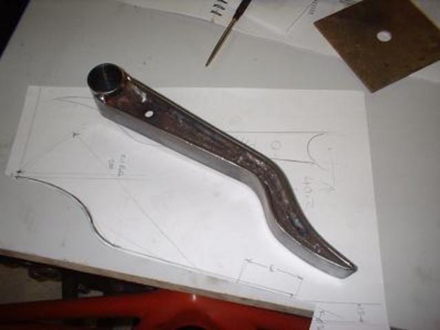
Rescued attachment DSCF0018small.JPG
|
|
|
MikeRJ
|
| posted on 1/9/08 at 11:54 PM |
|
|
quote:
Originally posted by LiamI made mine kind of like an I-beam. Sheet cutout profile like the roadster above, but with front and rear
strip faces for torsional rigidity. Certainly wont be worried about it buckling after a few panic brake efforts
Liam
Looks very nicely made, but welding that must have been quite tricky?
|
|
|
AlphaX
|
| posted on 2/9/08 at 01:02 PM |
|
|
Matt,
what effect does that stress have? Is it going to bend the entire pedal or is the pedal going to break or is it not going to do anything? It is
interesting to see where the stress-points are, but I feel that this doesn't matter in this situation.
How is the stress with 2x3mm steel plate instead of 1x5mm?
cheers
|
|
|


.jpg)