sgraber
|
| posted on 28/10/06 at 06:10 PM |

|
|
First chassis redesign- comments requested
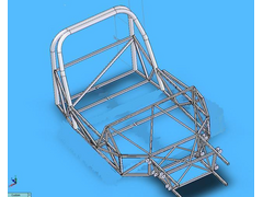
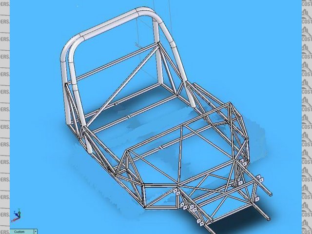
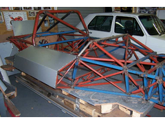
Based on my observations and comments made about my first chassis design, I have been diligently redesigning the passenger area of la Bala.
The plan is to do a semi-monocoque where there are no diagonal brace tubes but welded panels out of 16ga sheet. Those are not shown below.
I should also mention that the front superstructure is not finished in this drawing. I am more interested in comments regarding the redesign of the
roll-structure and rear firewall. Soon I will post more refined images of the front/windshield/dash structure for comment.
The area behind the firewall (triangle) is reserved for the fuel cell.
Calculated weight of this shown assembly is 117Lbs.

You may recall that I have a stepped firewall and a bolt-on roll-bar in the MKI version.

Steve Graber
http://www.grabercars.com/
"Quickness through lightness"
|
|
|
|
|
ned
|
| posted on 28/10/06 at 06:25 PM |
|
|
well someone's going to ask so it might as well be me:
whats the reasoning behind the semi-monocoque direction steve?
is it lighter, stiffer or easier to manufacturer than the traditional triangulated spaceframe?
cheers,
Ned.
beware, I've got yellow skin
|
|
|
JoelP
|
| posted on 28/10/06 at 06:27 PM |
|
|
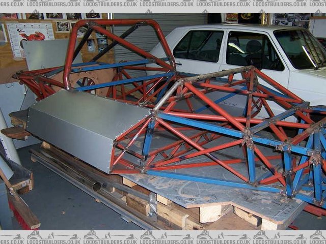
i appreciate it all has to fit under the existing bodywork, but would it be possible to add the red lines below? The front and back are held together
by a very narrow bit of frame. Also the usual triangulation where possible.
The front suspension box looks like it could use a few extra tubes to hold it to the middle bit, be damned if i can work out where would be good
though! With the absense of a tunnel structure down the middle its a little difficult. 
 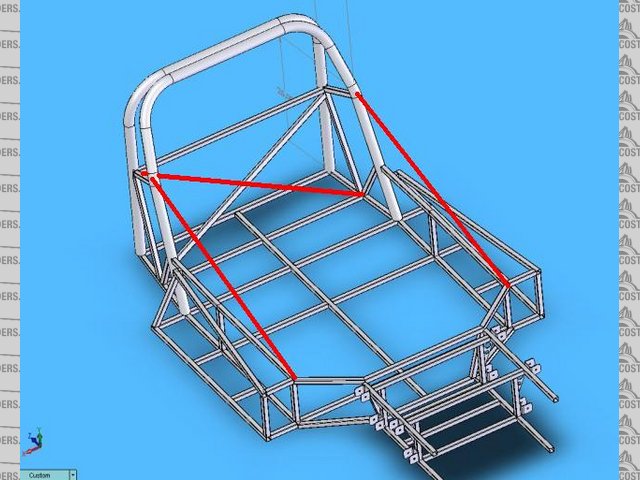
Rescued attachment graber1.JPG
|
|
|
sgraber
|
| posted on 28/10/06 at 07:47 PM |
|
|
Ned, the sides need paneling anyways so welding a sheet in place of a diagonal+sheet just seems to be simpler, lower on the parts count and since each
panel is welded in, stiffer too. Now that it's all coming out of the solidworks file I will be able to have each piece cut to fit perfectly
too.
Joel, the x-brace across the firewall makes perfect sense, thanks. The other braces you drew are premature because as I mentioned before the front
superstructure isn't complete. There is a side-impact/brace bar that will do just as you drew, but with greater side-impact protection. The
front susp. box is incomplete too.
It may have been premature to show this drawing, but I didn't want to get the entire way through the design/drawing and then have someone notice
a big error...
Steve Graber
http://www.grabercars.com/
"Quickness through lightness"
|
|
|
ned
|
| posted on 28/10/06 at 08:12 PM |
|
|
I may be out of my depth here but I know stiffness and strength are different and although panelling may give the same or greater stiffness in the
chassis structure how does it compare strength wise in terms of an accident or impact? I'd guess (but may be wrong) that a panelled square may
be weaker and fold up easier than a triangulated square?
Ned.
beware, I've got yellow skin
|
|
|
Spyderman
|
| posted on 30/10/06 at 02:17 PM |
|
|
Steve, my immediate thoughts would be more along the lines of how much more difficult it would be to avoid heat distortion during welding. If the
panels are to be structural then how they are welded would be far more crucial.
As those who have welded steel floorpans in will tell you, it is hard to avoid panel distortion. If the panel is distorted then it is not as
structural as you would hope.
To avoid the distortion you might move to preformed or pre-folded panels and spot welding. Thus negating the simplification that you sought in the
first place.
There are some kit manufacturers that have gone semi-moncoque steel chassis, but overall most still use the tried and trusted spaceframe method. Must
be a reason for this! 
Terry
Spyderman
|
|
|
kb58
|
| posted on 30/10/06 at 02:53 PM |
|
|
I agree about the welding distortion. TIG would definitely be better since it doesn't put as much heat into the panel. Or like suggested, spot
weld them.
One trick I saw to avoid distortion is to bend a thin lip upward around the edge of each panel, then slide it in between the tubes. Then, only the lip
is welded. I saw this in some book and while I understand how it avoids distortion, I'm not sure how well it would work. It seems like the bent
edges would act as hinges, allowing motion - not a good thing.
Mid-engine Locost - http://www.midlana.com
And the book - http://www.lulu.com/shop/kurt-bilinski/midlana/paperback/product-21330662.html
Kimini - a tube-frame, carbon shell, Honda Prelude VTEC mid-engine Mini: http://www.kimini.com
And its book -
http://www.lulu.com/shop/kurt-bilinski/kimini-how-to-design-and-build-a-mid-engine-sports-car-from-scratch/paperback/product-4858803.html
|
|
|
sgraber
|
| posted on 30/10/06 at 05:40 PM |
|
|
You are making a very good point guys. I got the idea to go with the stressed panels when I saw the JBL Motorsports Cobra replica at the last kit-car
show I went to. The frame was so nice it was simply heads above everything else I had seen. Granted it's a Cobra, and it's front engined,
and it's designed to accept 600Hp big block motors, but the basic concept of stressed skin seemed like a great idea.
You should take a look at the following site to see some cad drawings and some FEA test results for the frame I am talking about.
http://www.jblmotor.com/JBLchassis.html
In any case, there must be a 'correct' way to weld these panels to prevent distortion? Maybe MIG in a pre-determined weld pattern... I
notice the JBL chassis uses a whole bunch of short welds, no longer than about an inch each.
Steve Graber
http://www.grabercars.com/
"Quickness through lightness"
|
|
|
DIY Si
|
| posted on 30/10/06 at 05:48 PM |
|
|
That is probably the easiest but most time consuming way of doing it. Weld alternate sides an inch or so ata time. That way, by the time you get back
round to where you started it's cool. Also then leave a gap of an inch or so so you are basically stitch welding but slower. Also, as said tig
if poss will help.
Let your plans be dark and as impenetratable as night, and when you move, fall like a thunderbolt.
Sun Tzu, The Art of War
My new blog: http://spritecave.blogspot.co.uk/
|
|
|
Syd Bridge
|
| posted on 30/10/06 at 06:03 PM |
|
|
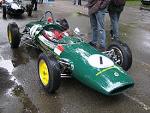
Have a good look at a 60's -70's Lola and similar racecar.
Then redesign the whole thing.
Bend the centre and front out of ali sheet and rivets. Bolt the back section on as a separate entity. Quick to do and light.
I did offer to do all this design stuff at the start of last year, or have you forgotten I exist? 
Regards,
Syd.
While you're at it, the front wishbone inner geometry is a bit cockeyed as well.
|
|
|
sgraber
|
| posted on 30/10/06 at 06:27 PM |
|
|
Where have you been hiding Syd?
You are correct about the front suspension geometry. Although the rails are placed correctly, those top brackets are definitely in the wrong
locations. Good catch. BTW I am reusing the geometry from my current front suspension for this chassis.
I'm curious to see some examples of the bent sheet construction. I have no experience with it. But I'm definitely open to any suggestions
that simplify construction, make the chassis stiffer, stronger and less expensive. (Expense that would include fabrication time of welding and cutting
tube)
Steve Graber
http://www.grabercars.com/
"Quickness through lightness"
|
|
|
ned
|
| posted on 30/10/06 at 10:25 PM |
|
|
this what you're on about syd?!
granted it's only a sports 2 but it is a lola and it is an ally tub with subframes front, rear and rollbar riveted to the folded, bonded and
riveted ally tub. yes it is an anchor of an engine but at least it's in the right place
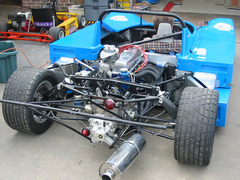 
Rescued attachment IMG_1146.jpg
beware, I've got yellow skin
|
|
|
grantmac
|
| posted on 3/11/06 at 12:54 PM |
|
|
I prefered the bolted on roll-bar myself, lets you adapt the design to different race sanctioning bodies much easier. Also lets you replace the bar if
you do have a minor roll.
Other than that it looks great just like the original.
Grant
|
|
|
THAWA
|
| posted on 3/11/06 at 02:16 PM |
|
|
What about a full monocoque instead of semi?
|
|
|
tadltd
|
| posted on 3/11/06 at 05:51 PM |
|
|
quote:
Originally posted by Syd Bridge
Have a good look at a 60's -70's Lola and similar racecar.
Then redesign the whole thing.
Bend the centre and front out of ali sheet and rivets. Bolt the back section on as a separate entity. Quick to do and light.
I did offer to do all this design stuff at the start of last year, or have you forgotten I exist?
---------------------------------------------------------
Wot Sid said!
You're more or less looking to do this:
 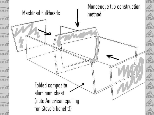
tub
Excuse the cr@p drawing - it was done on MSPaint in about 5 mins, but it gives the general idea. 3 solid bulkheads, one at each end and one in the
middle. These are usually cast or machined from solid on race cars, but it is possible to use tube and sheet to construct them. You then
'hang' front and rear subframes off these for suspension, engine, etc (as per Ned's pic).
[Edited on 3/11/06 by tadltd]
Best Regards,
Steve.
www.turnerautosport.com
|
|
|
tadltd
|
| posted on 3/11/06 at 05:59 PM |
|
|
 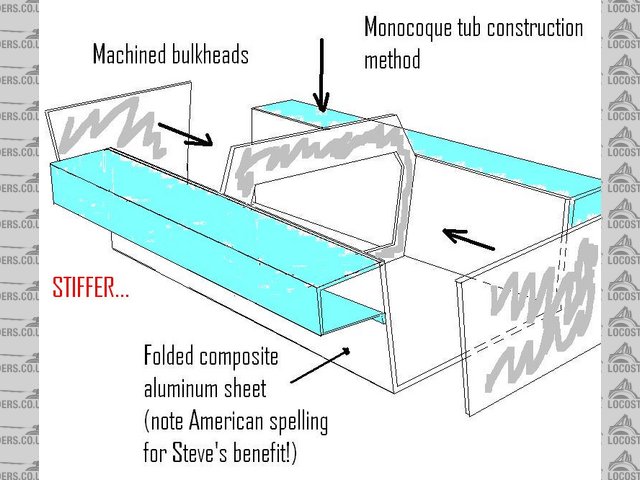
tub2
Best Regards,
Steve.
www.turnerautosport.com
|
|
|
sgraber
|
| posted on 4/11/06 at 12:33 AM |
|
|
That's beautiful work as usual Steve! And in paint no less. Wow. Plus I am actually able to read it straight off without referencing my handy
UK/USA translation booklet! wow.
But seriously. That's really good and it sets my gears spinning in a whole new direction. Like I didn't already have enough to think
about?!
Thanks.
Steve Graber
http://www.grabercars.com/
"Quickness through lightness"
|
|
|
Ratman
|
| posted on 4/11/06 at 12:51 AM |
|
|
My comment on triangulation vs sheet-material is that the loads imposed on the structure are generally at points. e.g. suspension bushes, engine
mounts. So, for the sheet material to accept these loads efficiently, there has to be some way of spreading the point load (say 300kg) into 2mm thick
material in three planes. This is the real challenge. It is so much easier just to link all the pick-up points up with straight tubes or similarly
structurally determinant tension/compression elements. I think the real benefit from monocoque construction comes when the sheet material serves more
than one function. e.g. crash safety, weather protection, fire proofing, etc. Cheers, Brian
|
|
|
cymtriks
|
| posted on 5/11/06 at 10:01 PM |
|
|
thoughts on La Bala spaceframe
This is the La Bala chassis but with some minor modifications.
Sme of the less useful tubes have been removed and some refinement of the triangulation has been added.
Rescued attachment SW-Frame-Stage1.jpg
|
|
|
cymtriks
|
| posted on 5/11/06 at 10:21 PM |
|
|
This shows a different approach to the engine bay.
A large section beam runs along the sides and rear of the engine bay (4x2 14g might be suitable), there are two diagonals at the sides which support
the main beam (possibly in 2x2 14g) and two diagonals to prevent lozenging (possibly 1x1 14g)
The brackets for the rear suspension rocker arms and watts links are shown and the links/rockers are in pink. These would need to be arranged so as to
prevent fowling of the links by the springs but it should be possible.
If you add up the tubes in the current frame it probably doesn't weigh much more les, if any less at all, than this concept and this concept is
much simpler.
Rescued attachment SW-Frame-Stage2.JPG
|
|
|
russbost
|
| posted on 6/11/06 at 02:02 PM |
|
|
Steve
I've been having similar fun & games with my new chassis for the Furore f1, altho' a very different general shape it has a similar
problem that the height of the rear (engine bay) section is substantially different to the cockpit/passenger area, I have added some extra
triangulation above the lower area joining to the higher area to spread the load & I feel yours would need similar - otherwise you have a major
weakpoint where the low & high sections meet - I realise this may cause you problems with the bodywork, but sometimes aesthetics have to be
sacrificed for strength, or at least a compromise made.
Also I would go for spaceframe over stressed welded panels everytime, simpler, cheaper to manufacture & probably lighter too.
Don't you just love comments like "throw it all away & start again" - you can tell they're not doing the work!
Great project, good luck with it.
I no longer run Furore Products or Furore Cars Ltd, but would still highly recommend them for Acewell dashes, projector headlights, dominator
headlights, indicators, mirrors etc, best prices in the UK! Take a look at http://www.furoreproducts.co.uk/ or find more parts on Ebay, user names
furoreltd & furoreproducts, discounts available for LCB users.
Don't forget Stainless Steel Braided brake hoses, made to your exact requirements in any of around 16 colours.
http://shop.ebay.co.uk/furoreproducts/m.html?_dmd=1&_ipg=50&_sop=12&_rdc=1
|
NOTE:This user is registered as a LocostBuilders trader and may offer commercial services to other users
|
Fred W B
|
| posted on 6/11/06 at 03:26 PM |
|
|
I'm using a combination of space frame and pressed up ally panels. The pressed side boxes panels added a lot to the torsional stiffness, if you
recall. see here
Cheers
Fred W B
df canamsa proto side pod
[Edited on 6/11/06 by Fred W B]
|
|
|
sgraber
|
| posted on 6/11/06 at 07:15 PM |
|
|
Great suggestions cymtriks. Your rear engine cradle looks 'exactly' like one I built out of balsa several years ago, but I couldn't
figure out how to get the roll center for the deDion low to the ground. The pivot point is the roll-center.
I have some suprises in store for your wrt the chassis. A lot less small tubes replaced with some larger ones, An aircraft style bulk-head (like
Terrapin), some stressed skin panels (like Freds) and more. I won't post it up until I can get a bit more work done on it.
I may switch over to a full monocoque at some future time, but for right now it's too much of a redesign for where I need to be in the next
month or two.
Steve Graber
http://www.grabercars.com/
"Quickness through lightness"
|
|
|
sgraber
|
| posted on 7/11/06 at 04:36 PM |
|
|
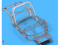
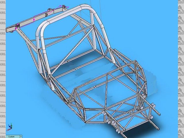
Here is a new image and the associated e-drawing of the new frame design - MINUS the paneling, which should add significant stiffness.

Steve Graber
http://www.grabercars.com/
"Quickness through lightness"
|
|
|
sgraber
|
| posted on 27/11/06 at 01:15 PM |
|
|
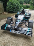
Here's another one. Completely new design for the passenger compartment. Weighs approx 50Lbs less than the previous designs.

Steve Graber
http://www.grabercars.com/
"Quickness through lightness"
|
|
|