rpmagazine
|
| posted on 14/2/07 at 10:22 AM |

|
|
Chassis design
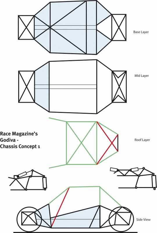
Here is a copy of Godiva's chassis design, which is detailed in Race Magazine. Note some changes have occurred since this drawing as a result of
working with a full sized mock-up of the chassis...what looks good on paper does not mean that components will match it!
|
|
|
|
|
rpmagazine
|
| posted on 14/2/07 at 10:40 AM |
|
|
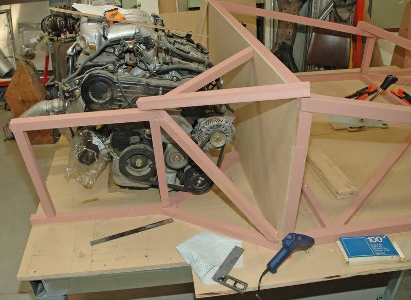
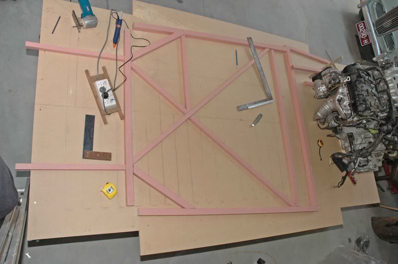
mock-up one:
|
|
|
SeaBass
|
| posted on 14/2/07 at 01:52 PM |
|
|
Looks interesting...
What is Race magazine - an american publication?
Has anyone got a CAD copy of the chassis?
What bodywork is involved
What is the car designed for - a road / track toy or a formula racer type??
|
|
|
Doug68
|
| posted on 14/2/07 at 10:25 PM |
|
|
Race magazine is a Australian publication.
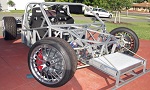
What you are seeing here is the 1st example in the prototype phase.
The engine BTW is a Mitsu 3.6L? V6.
I'm sure rpmmagazine will explain further...
|
|
|
rpmagazine
|
| posted on 15/2/07 at 01:26 AM |
|
|
Seabass, Race Magazine (actually Race Performance and Car Constructor Magazine) is as Doug posted an Australian quarterly magazine that has been going
for 2 years. I am the Publisher.
Project Godiva is the project car within the magazine and is an ICV (individually constructed vehicle) designed to meet the relevant australian
standards so it can be run on the road. As such it is not intended to be a lemans style car. It is intended to be a car that you can drive to an event
should you wish and it is focused at tarmac rallies (e.g. Targa Tasmania), circuit racing/sprinting, Hillclimbs etc.
There is no CAD copy of the chassis as it is constantly getting modified as the component list is finalised. I am in essance reverse engineering
aspects of the above design as the final dimensions of components are realised. An example of this is the steering rack: 3 were tried, each with a
different width and each required the front box and the cabin area to be changed to suit the new chassis dimensions.
There was the intention to publish a manual with a DVD with all of the plans on it so that they could be printed off full size on a plotter. This is
on indefinate hold as the dreaded insurance issues have raised their head.
The dimensions are (note this may vary slightly as you would expect):
wheelbase 2570mm
rear track 1570mm
front track 1630mm
height 1250mm
weight 880-900kg
the engine is a Mitsubishi 3.8lt 6g75 with a 5 speed close ratio manual gearbox, which gives 175kW as std.
|
|
|
Ivan
|
| posted on 15/2/07 at 07:20 AM |
|
|
An exciting project. 
I'm always interested in these types of projects (as I am sure are many others) Please keep us updated on progress on this thread.
|
|
|
locost_bryan
|
| posted on 16/2/07 at 03:31 AM |
|
|
quote:
Originally posted by rpmagazine
the engine is a Mitsubishi 3.8lt 6g75 with a 5 speed close ratio manual gearbox, which gives 175kW as std.
180kw in the VR-X and GT in NZ - exhaust changes iirc
Didn't Mitsi do a Supercharged engine for one of the motor shows?
Bryan Miller
Auckland NZ
Bruce McLaren - "Where's my F1 car?"
John Cooper - "In that rack of tubes, son"
|
|
|
rpmagazine
|
| posted on 16/2/07 at 08:58 AM |
|
|
Yes, there was a supercharged 6G75 in the TMR 380, which is a motorshow special. The Sprintex kit for the 6G74 is freely available and can take power
up to 280kW, but at these levels the transmission will require care and attention as the diff is a weak point. Mind you using the engine/box mid mount
will change the loads etc on it, so the issues may be different and only time and failures will show what needs to be fixed.
I expect a new intake cam, mild port work and better ex/induction will give around 205kW, though of course this will not be legal. A more radical
rebuild should net 220kW or so, but it gets expensive, say a $6k modification not including ECU.
To be honset the money is far better spent on very good dampers as these will allow more speed and better braking, hence my current thoughts are
leaning towards Penske dampers.
|
|
|
rpmagazine
|
| posted on 18/2/07 at 02:27 AM |
|
|
FWIW the Race Magazine looks like this:

[Edited on 18/2/07 by rpmagazine]
|
|
|
rpmagazine
|
| posted on 17/7/07 at 11:55 AM |
|
|
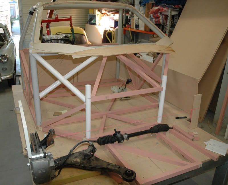
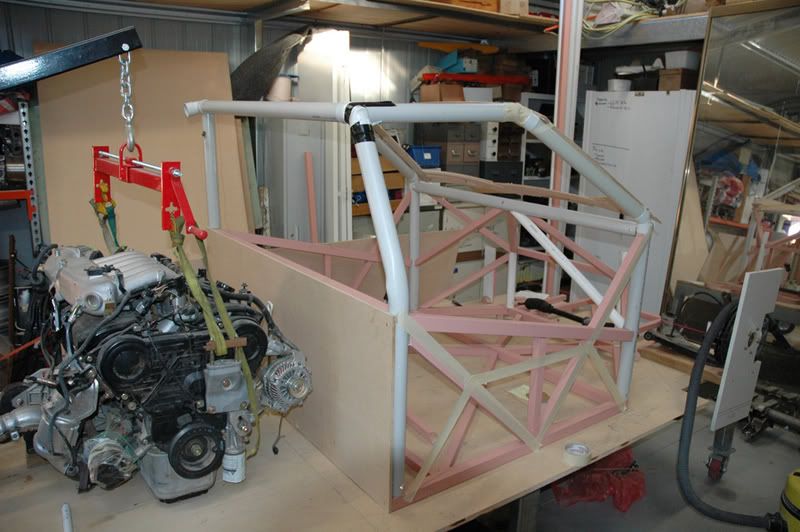
Time holds still for now man and especially a car builder!
Here are some more picks showing some progress...it has moved on from here and the mock-up is almost finished.
|
|
|
Doug68
|
| posted on 18/7/07 at 11:01 AM |
|
|
That's coming along, it looks good and tall though, whats the expected height going to be?
I'm sure you've thought of it but the diagonals coming down from the center of the windscreen look like they'll be argro on the
legs.
|
|
|
rpmagazine
|
| posted on 18/7/07 at 12:59 PM |
|
|
The looks are deceiving, as the car will be 911/cayman height at 1280-1315mm.
The diagonals are also far worse looking than they really are, there is plenty of room for me and I cannot expect anyone else will need more room!
The front and rear structure ties in nicely, but I cannot show that yet. The side structure will likely change to where the tape is. Plan is to exceed
60kN/deg for the chassis.
The mockup structure was changed to increase the stiffness. I adapted a trick from Ron Tauranac, which was to make the structure and then run tightish
tape lines where I thought tubes should go. I then pushed on various points to simulate the running forces and the tapes went tight/slack at different
points. This showed where structure needed to be added.
The main cage tubes are 50mm cds and the sides are 50mm SHS 1.6mm wall 450mpa with the smaller tubes generally 40mm of the same.
[Edited on 18/7/07 by rpmagazine]
|
|
|
Doug68
|
| posted on 18/7/07 at 01:45 PM |
|
|
Where'd you get the 450mpa steel from?
I had to go with 350mpa here in WA,
The 450mpa grade material I found in catalogues was One Steels HiLite series which seems basically impossible to get over here.
|
|
|
rpmagazine
|
| posted on 19/7/07 at 09:28 AM |
|
|
Hi Lite is available in Vic. The performance of Palmer tube mills (now Smorgon steel) dual grade 350Lo/450Lo is also good and it is supposedly easier
to weld. The Hi Lite is available in 1.2mm wall in the catalog, but finding it in small quantities is the trick. Smorgon's will only sell in a
bundle as a minimum and no one need 50 tubes 6m long!
Mind you if you are in WA then Ayres Panels is 'local'.
|
|
|
rpmagazine
|
| posted on 27/7/07 at 11:52 AM |
|
|
Doug, I've been told that there is a 450mpa Duragal in 1.6mm wall. I've been given some samples of it and the galvanising zinc is also on
the inside of the tube...good for chassis survival.
|
|
|
Doug68
|
| posted on 27/7/07 at 02:52 PM |
|
|
That's a bit blinking late for me now!

|
|
|
rpmagazine
|
| posted on 27/7/07 at 10:49 PM |
|
|
Coming on there!...have you sat in it yet making brumm brumm noises? Maybe that is just me and my two young boys!
How are you holding it down to the checker plate?
I was planning to tack weld tubes down.
|
|
|
Doug68
|
| posted on 28/7/07 at 02:36 PM |
|
|
It tacked down to the checker plate in various places. Using the TIG to do that for some reason was just not happening, so I broke out the arc rods
and got it tacked down that way.
Just tonight I finished tacking all of the floor tubes in place. Now I get to start on fully welding it together.
|
|
|
rpmagazine
|
| posted on 29/7/07 at 10:37 AM |
|
|
Interesting. Did you find it moved much from the weld and weld contraction when tacked down?
BTW Godiva's rear suspension should be heading down the path as per this image:
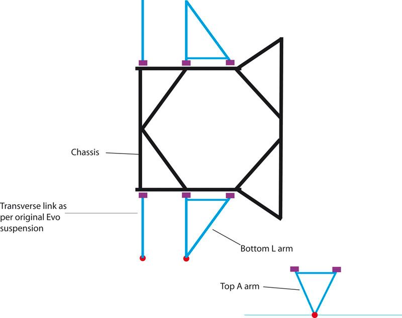
I've also decided to follow the advice I've been given and will go for suspension bushes on the inner pivots of the arms, though the cost
saving is not as good as you might think.
This will lessen the impact/shock loads and will allow development without the mount/arm/chassis fatigue concerns.
[Edited on 29/7/07 by rpmagazine]
|
|
|
Doug68
|
| posted on 29/7/07 at 12:56 PM |
|
|
When tacking it down I was unable to detect any movement off alignment marks. I'm sure it did move but not enough to measure.
Obviously I was aiming to get as little heat into the tube as necessary.
I'm using these for inner rod ends on the to "A" arms...

My reasons why are here
[Edited on 29/7/07 by Doug68]
Doug. 1TG
Sports Car Builders WA
|
|
|
kb58
|
| posted on 29/7/07 at 05:28 PM |
|
|
Those will work fine as long as they aren't being asked to move off centerline much.
Mid-engine Locost - http://www.midlana.com
And the book - http://www.lulu.com/shop/kurt-bilinski/midlana/paperback/product-21330662.html
Kimini - a tube-frame, carbon shell, Honda Prelude VTEC mid-engine Mini: http://www.kimini.com
And its book -
http://www.lulu.com/shop/kurt-bilinski/kimini-how-to-design-and-build-a-mid-engine-sports-car-from-scratch/paperback/product-4858803.html
|
|
|
rpmagazine
|
| posted on 29/7/07 at 10:51 PM |
|
|
They seem a good compromise and get away from the jarring and wear issues that some rods ends develop.
I may end up using MX5 front wishbone bushes in most places, though the lower arm may have added longitudinal compliance.
|
|
|
Doug68
|
| posted on 30/7/07 at 12:49 AM |
|
|
Yep in the design my end should need to only rotate about the bush.
If it needs to do anything else its a stuff up on my part.
|
|
|
rpmagazine
|
| posted on 30/7/07 at 10:45 AM |
|
|
well there is a little bit of compliance in that bush. Getting them to line up perfectly can be quite tricky. According to some you can tailor the
compliance of a poly bush by removing some of the material or by casting your own dual durometer bushes...quite a bit of work though and potentially
hard to replicate when they wear out.
|
|
|
rpmagazine
|
| posted on 12/8/07 at 12:12 PM |
|
|
Some updates...and some details I am not really happy about:
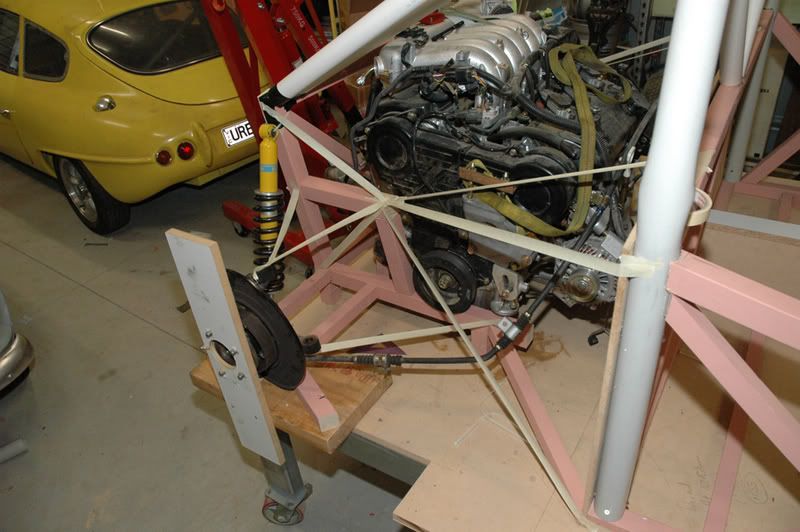
The tape represents structural members and suspension components.
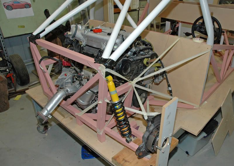
The inner bit of tape attaching on the bottom tube is a removable diagonal from the front mid tri-node.
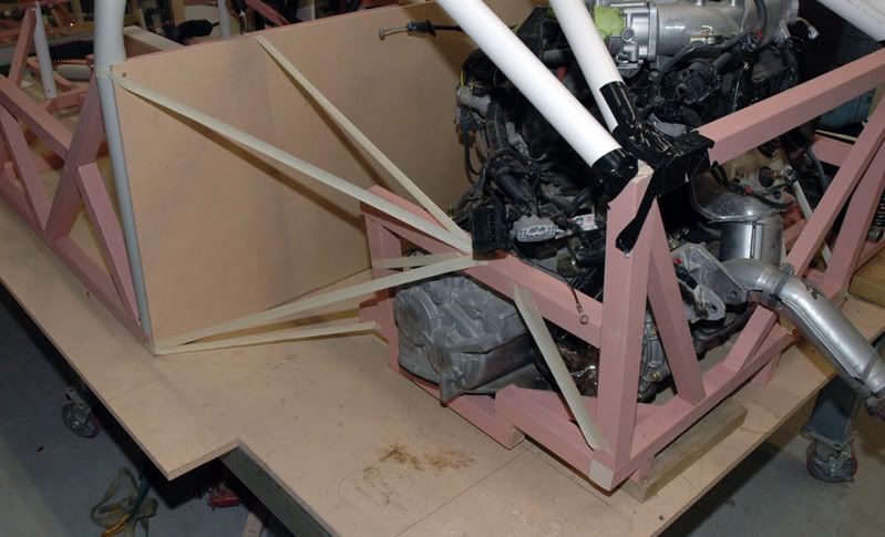
Really not happy about the dogleg in the structure...it would not be made this way, but that gearbox creates some problems!
[Edited on 12/8/07 by rpmagazine]
|
|
|