Blacktop
|
| posted on 5/11/07 at 03:29 PM |

|
|
Newbie mid engined project
Hello, Newbie here so be kind
I am going to be building a mid-engined buggy probably powered by either a 1.4 or 1.6 Rover K-Series. The buggy is not intended for track use so
decided against a BEC.
I have an idea for the body which will be a hacked up & modified beach buggy shell.
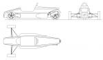
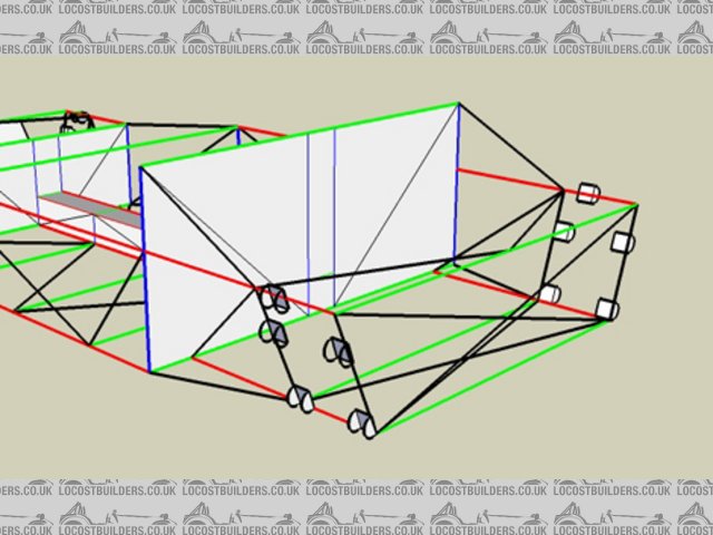
Here are some rough pics of ideas for the chassis. I am also still learning Sketchup so these may improve as time goes by.
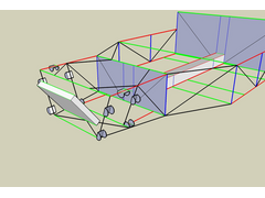 
ChassisFront
 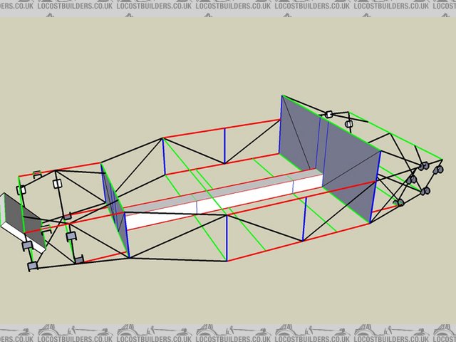
ChassisMiddle
 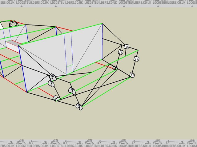
ChassisRear
|
|
|
|
|
Spyderman
|
| posted on 7/11/07 at 12:58 PM |
|
|
Hi Blacktop and welcome.
Your buggy sounds interesting and is something I have considered many times, being a beech buggy fan.
I am assuming your chassis is meant to be a more modern version of the VW floorpan?
If so, how are you planning on mounting the body to the chassis?
At least you will have the luxury of having removable side panels. 
I'd also be interested how you hope to wheel your buggy? Traditionally buggys have at least 15 inch rims with high profile fat rubber on them.
What about gearing/gearbox options? Typical old Beetle gearing is very low for low power high torque engines.
Not insurmountable problems I'm sure, but just curious how far you have planned. The last two questions being closely related.
I look forward to seeing how your car progresses! 
p.s. Just a minor note on your chassis pics.
You need to put triangulations into junctions, not the middle of straight runs. Have a look at others chassis renditions and you will see what I
mean.
If your central tunnel is meant to be a structural aspect then you will need to triangulate it into the chassis front and rear. If you just want it as
a conduit for gear linkage etc then fine, but you may as well make it structural.
Not meant as criticisms, just observations.
[Edited on 7/11/07 by Spyderman]
Spyderman
|
|
|
designer
|
| posted on 8/11/07 at 09:00 AM |
|
|
Totally agree.
eg. The triangulations from the coil/over mounting brackets should join in the middle of the front, top front crosspiece.
|
|
|
Blacktop
|
| posted on 12/11/07 at 10:00 AM |
|
|
Thanks for the replies
I am making some amendments to the chassis design, I will post some pics up later.
Spyderman - to answer your questions
The fibreglass body will be chopped and modified to create a front and rear clamshell which will be removeable.
I plan on running 17" wheels on low profile rubber.
Gearing/Gearbox - I will be using a transversely mounted k-series engine and gearbox like a Lotus Elise & MGF.
|
|
|
designer
|
| posted on 20/11/07 at 07:19 PM |
|
|
17" wheels on low profile rubber along with firm suspension will mean a very hard ride.
|
|
|
smart1275gt
|
| posted on 20/11/07 at 07:29 PM |
|
|
Have you checked out www.muddybuggies.com? There is a K series being built on there.
Good luck, oh yeah, Welcome!
|
|
|
Blacktop
|
| posted on 27/11/07 at 10:53 AM |
|
|
Ok, I have managed to get round to making some changes to the chassis design.
Here are the pics
 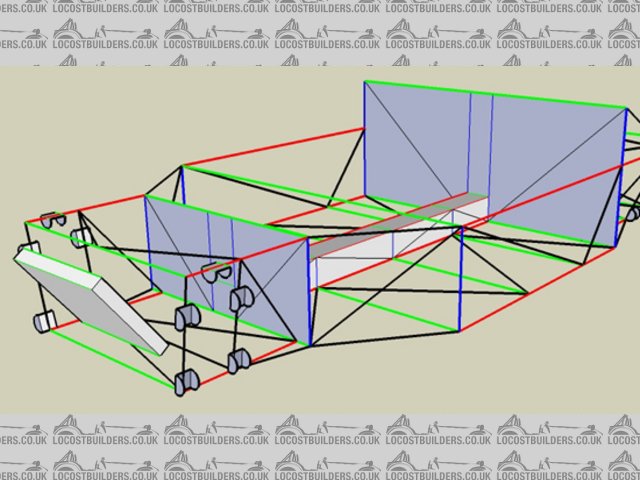
ChassisFront1
 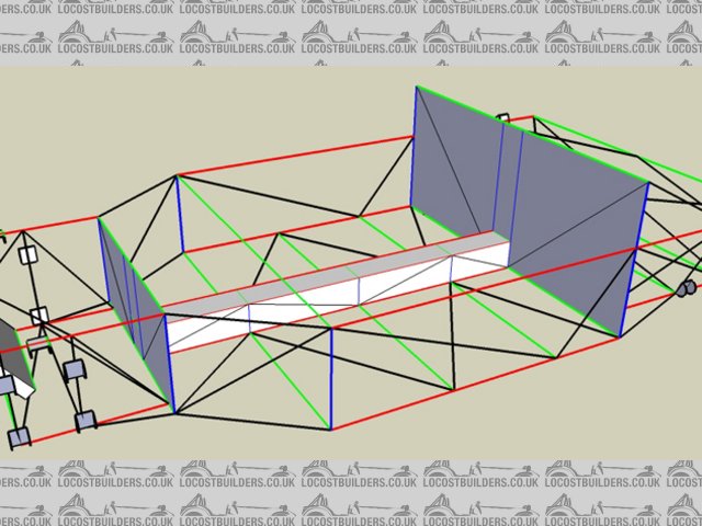
ChassisMiddle1
ChassisRear1
|
|
|
Doug68
|
| posted on 27/11/07 at 12:52 PM |
|
|
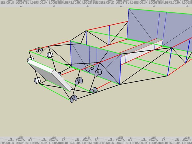
I guess I'll begin, remember this is just my opinion which is easy to dismiss, most people do...
See numbers below...
1. Black uprights look too vertical for wishbone layout (maybe deciding suspension geometry first is an idea). Make blue and black uprights parallel
then nasty bottom corner can be done away with.
2. Looks like a vertical should be in there to support the red tube from buckling when it's in compression. And to take the load from point
5.
3. Shock top loads and chassis twisting loads will come in through this area. Brace the heck out of it.
4. Nasty corner to be removed, see point 1.
5. Compression load in black diagonal needs to go somewhere, suggest a diagonal down to the verticals in point 2.
6. Loads need to go into something on the other side of the bulkhead.
7 and 8. X looks too shallow, hole in front may be bigger than needed for sump? Possibly make wishbones wider to be able to support them closer to
bulkhead and possibly brace around front of engine to support mounting area.
Also is the tunnel cosmetic or structural? If structural make it as deep as possible.
Have you made a balsa model yet? Without doing that or FEA instead these are all wild ass guesses of course.
 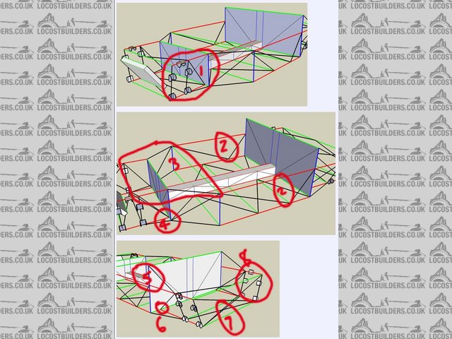
Rescued attachment Markup.jpg
Doug. 1TG
Sports Car Builders WA
|
|
|