Rudy
|
| posted on 3/9/23 at 01:23 PM |

|
|
Speeduino
Hi,
are someone running on speeduino ?
I was thinking to put a speeduino system on my Tiger zetec silverhead, now I am running with original ford mondeo ecu and would like to try to play
with the management of the engine.
I am at the beginning of the project so any advice is appreciate.
Sorry about my English
Rudy
Sorry about my English
|
|
|
|
|
scudderfish
|
| posted on 3/9/23 at 02:56 PM |
|
|
I use it to run my V8. It works really well, much better than the MS1 it replaced. Just make sure you read all the docs. I found it a good help to
install it on an Arduino, add a simulator board and fiddle with it on the desk.
|
|
|
Sanzomat
|
| posted on 3/9/23 at 07:34 PM |
|
|
I'm on speeduino on my R1 engined Locost. Works a treat and the rolling road who mapped it for me were also fine with it.
|
|
|
robocog
|
| posted on 3/9/23 at 08:23 PM |
|
|
I think I'm about to go on that journey...
car is currently running MS1extra and EDIS
Got an arduino mega, flashed it and had a play in tuner studio...am impressed so far
My hold up is deciding which board to go with
Was looking at building a NO2C, but lack of finding a suitable off the shelf (non 3d printed) enclosure is making me wonder if one of the other 4ch
boards will be more suitable
(even though I am unlikely to play with sequential and 2channels for spark/fuel is all I will ever likely need or use)
EDIS has been rock solid, and the MS1 has done a fine job for a long time...
BUT
I am fighting for resolution at low throttle openings where it seems I possibly need a few more bins to reduce the compromises
Speeduino will give me a few more bins(16*16 v 12*12) whether that is enough to "fix" the minor gripes I have..
Seems a no2c will let me find out for not much money, so is looking pretty attractive....
|
|
|
scudderfish
|
| posted on 4/9/23 at 05:53 AM |
|
|
I bought one of these https://diy-efi.co.uk/product/diy-efi-core4-te36
|
|
|
scudderfish
|
| posted on 4/9/23 at 05:53 AM |
|
|
quote:
Originally posted by Sanzomat
I'm on speeduino on my R1 engined Locost. Works a treat and the rolling road who mapped it for me were also fine with it.
Where did you get it mapped?
|
|
|
Sanzomat
|
| posted on 4/9/23 at 07:26 AM |
|
|
quote:
Originally posted by scudderfish
quote:
Originally posted by Sanzomat
I'm on speeduino on my R1 engined Locost. Works a treat and the rolling road who mapped it for me were also fine with it.
Where did you get it mapped?
Link
Badger 5 - they are mainly a VAG specialist but will take on most things and a friend of a friend who puts speeduinos into scoobies recommended them
and sat in for the mapping session
|
|
|
coyoteboy
|
| posted on 4/9/23 at 08:09 AM |
|
|
Been quite keen to try a speeduino but I always find things that niggle with the boards and spark/ful control options - they're never quite what
I want. Have they got it working on a higher pinout chip yet to allow fully sequential V8 - I know the firmware used to support it but when I checked
there were no CPUs/duinos with enough pins. I'd like a LOT more power conditioning and signal safety and conditioning than is available on most
of the boards - having binned one engine due to a spurious signal on a hall-effect crank pickup (shielded, twisted pair grounded at the ECU) I'm
curious as to whether they have windowing on input signals to mask spurious inputs.
|
|
|
Rudy
|
| posted on 4/9/23 at 11:28 AM |
|
|
thankyou,
so I am going to buy an arduino mega and install the software, play with tuner studio ...
Does anyone have a zetec silvertop running on speeduino? If yes may I have the map Just as a starting point ?
Sorry about my English
|
|
|
robocog
|
| posted on 6/9/23 at 06:32 AM |
|
|
Just placed an order for the no2c board and VR conditioner
Will deal with how to case it when it is here, built and tested....
Will report back
|
|
|
coyoteboy
|
| posted on 7/9/23 at 12:56 PM |
|
|
If I were you I'd look at ways of properly mounting add-on boards like VR conditioners and DBs. The biggest weakness I found with the MS (and it
looks to be similar for the various speeduino boards, from a glance) is that add-ons are done via horrible "spit wad" push-on solutions,
have no proper mechanical support and really should be a part of the board in the first place. Then the enclosure and connectors/wiring are the second
downfall of almost every beginner user. cheapo D-subs and header pins everywhere. No high-reliability product was ever designed that way, and
that's what you need. It's possible to do a speeduino board cheaply, small and with every option built in and just DIP switched out/in as
required.
|
|
|
MikeR
|
| posted on 7/9/23 at 03:41 PM |
|
|
I actively develop the speeduino firmware by adding in new decoders so it will support more engines. The standard silvertop is a 36-1 (missing tooth)
pattern that is supported. If you wanted to get fancy and do VVT (i think thats the st170) it also supports that.
The key thing after reading and reading is to get the trigger settings right. The biggest mistake people make is to confuse trigger edge and wiring.
The two are related but the key relationship is between the VR conditioner and the trigger edge. They are absolutely linked and you must set the edge
to match the conditioner. You then swap the wiring around till you get the correct looking signal in high speed logger.
That then sets you up to do everything else.
Their are a lot of boards now, you've got the original v0.4 and no2c based on the arduino mega. These will work fine for you. People have started
using faster processors with more pins which allows them to do v8 sequential ignition and fuel. Generally these are STM or Teensy based. The person
who started the whole speeduino movement introduced a new board "dropbear" (he's Australian, don't ask). Unfortunately this was
based around a teensy 3.5 chip that stopped getting made at the end of the pandemic. He's almost finished redoing the board to be based on a
teensy 4.1.
So in summary, it will do what you want, their are upgrade paths to faster boards if you ever needed it.
A good source in the UK is DIY-EFI. He's affiliated to the speeduino group. If you do buy that affiliation means your board will work with future
firmware releases. Non affiliated means you'll have to do a download, compile and burn yourself. The software does approx 1 release a year but
will do maintenance fixes if necessary inbetween major releases.
|
|
|
coyoteboy
|
| posted on 7/9/23 at 03:46 PM |
|
|
quote:
Originally posted by MikeR
I actively develop the speeduino firmware by adding in new decoders so it will support more engines. The standard silvertop is a 36-1 (missing tooth)
pattern that is supported. If you wanted to get fancy and do VVT (i think thats the st170) it also supports that.
The key thing after reading and reading is to get the trigger settings right. The biggest mistake people make is to confuse trigger edge and wiring.
The two are related but the key relationship is between the VR conditioner and the trigger edge. They are absolutely linked and you must set the edge
to match the conditioner. You then swap the wiring around till you get the correct looking signal in high speed logger.
That then sets you up to do everything else.
Their are a lot of boards now, you've got the original v0.4 and no2c based on the arduino mega. These will work fine for you. People have started
using faster processors with more pins which allows them to do v8 sequential ignition and fuel. Generally these are STM or Teensy based. The person
who started the whole speeduino movement introduced a new board "dropbear" (he's Australian, don't ask). Unfortunately this was
based around a teensy 3.5 chip that stopped getting made at the end of the pandemic. He's almost finished redoing the board to be based on a
teensy 4.1.
So in summary, it will do what you want, their are upgrade paths to faster boards if you ever needed it.
A good source in the UK is DIY-EFI. He's affiliated to the speeduino group. If you do buy that affiliation means your board will work with future
firmware releases. Non affiliated means you'll have to do a download, compile and burn yourself. The software does approx 1 release a year but
will do maintenance fixes if necessary inbetween major releases.
VR pickup polarity, shielding and trigger setup was always the thing that caught out MS users too - not sure why, it's fairly simple to work
methodically through. Good to hear there's faster boards with full Seq capability now - it opens it up for me making my own power/IO board and
dropping it onto my S8 engine.
|
|
|
MikeR
|
| posted on 7/9/23 at 04:21 PM |
|
|
I got frustrated with the repeated questions so edited the wiki a few weeks ago to try to make it clearer. Historically it's not been clear, so I
get why the confusion. But if you understand the rules as I posted above it's easy.
(I might edit the wiki again add I saw a great example of good and bad tooth logger to make it even more clear when you've got the wiring right)
|
|
|
robocog
|
| posted on 7/9/23 at 04:56 PM |
|
|
quote:
Originally posted by MikeR
...
The key thing after reading and reading is to get the trigger settings right. The biggest mistake people make is to confuse trigger edge and wiring.
The two are related but the key relationship is between the VR conditioner and the trigger edge. They are absolutely linked and you must set the edge
to match the conditioner. You then swap the wiring around till you get the correct looking signal in high speed logger.
I have ordered the NO2C and the VR conditioner from DIY-EFI - not arrived yet
It is going on a silvertop zetec, not bothering with cam trigger as it wont do sequential, being only 2 ch
Not sure which conditioner board I will receive yet but I have read this, which is what I assume you are referring to
______________________________________________________________________
Trigger edge - Whether the primary signal triggers on the Rising or Falling edge.
VR Conditioners require specific setting depending on model used:
VR conditioners based on MAX9926 or LM ICs should use RISING. This includes Dropbear units
DSC conditioners should use FALLING
-----------------------------------------------------------------------------------------------------------------
I also know what the polarity of the VR sensor I have /should be/ (is working fine with EDIS)
Hoping it will be straight forward to identify which VR conditioner I get, and that it all works without too much drama
I know it is a 36-1 tooth pattern on the crank
The only bit I am unsure of is the trigger angle on the stock zetec silvertop (always had EDIS holding my hand and doing the hard work for me  ) )
ST170 page on the speeduino site suggests 90...
and a megasquirt page suggests "36-1 wheel aligned the same as EDIS4 (see EDIS pages) trigger angle=60 "
and another edis page from megasquirt "EDIS-4: missing tooth is exactly nine teeth (90°) ahead of the VR sensor (at cyl1 TDC)"
I will likely try at 90 degrees first and see what the timing light thinks...
|
|
|
MikeR
|
| posted on 7/9/23 at 05:25 PM |
|
|
Hints and tips incoming.
Mega squirt is not speeduino. They do things differently. Do not rely on internet wisdom. Figure out for yourself (eg one does btdc the other users
atdc so 90 in one is 270 in the other).
Forget what you think the polarity is, configure edge for the vr sensor and test until the high speed trigger log for primary tooth looks correct.
NB I don't know electronics nor tuning, I just know the code. I have picked up a wealth of bits of knowledge from helping to get the decoder
I've written running.
|
|
|
Rudy
|
| posted on 15/9/23 at 02:41 PM |
|
|
... I bought an arduino mega 2560 and I am trying do do some step,
1 speeduino firmware installed
Tuner studio installed on my pc
speeduino base tune. msq charged
I am esploring tuner studio and seems I will be able to play with
Can someone indicate where I can download a zetec silverhead file.msq to play with as a starting point?
Thankyou
I know, I am making maybe silly question, I am in the beginning with speeduino but have some base knowledge in my luggage
Sorry about my English
|
|
|
MikeR
|
| posted on 15/9/23 at 03:13 PM |
|
|
Please don't assume something you find is correct. Things like vr conditioner affect the trigger edge which could move the timing by 10 degrees.
The base tune should get the engine started fire you to start tunning.
The community is starting to use a central repository for loading log files and tunes. People normally do that when they have a problem. Is love to
share the link but I can never remember where it is!!!
|
|
|
MikeR
|
| posted on 15/9/23 at 03:14 PM |
|
|
Should have added, JAMA who runs diy-efi did the code for vvc on the zetec so he may have something to start with.
|
|
|
robocog
|
| posted on 15/9/23 at 04:49 PM |
|
|
My NO2C has arrived
Not had chance to solder it up yet..but looks pretty straightforward
I have been working through TS for speeduino and the manual, as you rightly point out speeduino is NOT MS...
Found a few bits and bobs that would have caught me out if I had gone into it with my MS hat on...
Hoping I get a chance to solder the board up this weekend
I doubt I will get round to trying it in the car for a while...ideally want to be doing it with the option of being able to revert back to MS and EDIS
easily...
But don't fancy remaking the whole loom if I don't have to ...and still haven't sourced a case or decided what plug style I want
Not finding much for what settings for the bosch 200 dual igniter module yet for speeduino and don't want to make assumptions that I find in
relation to MS
(have messaged diy-efi where I got it all from for some clarification/suggestions)
Add to that I had a quick look over the car whilst mulling over how to swap ECU with minimal hassle/disturbance and noticed some of the fuel lines
have got some cracking to the outer rubber already...less than 2 years on the car...only ever filled with e5 (which the garage I fill up from reckons
they don't put any ethanol in.. yet)
I have a clear filter which has black speckles in...I am guessing the inside of the pipes is also letting go...sigh
..so got other stuff that I need to sort first
|
|
|
MikeR
|
| posted on 15/9/23 at 05:44 PM |
|
|
Found the tunes site. No zetec unfortunately.
https://tunes.speeduino.com/
|
|
|
robocog
|
| posted on 17/9/23 at 08:34 AM |
|
|
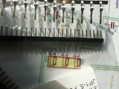
NO2C is all soldered up and a bit of basic bench functionality testing...
Have tested the map sensor and that is fine
Got the Ign1 and 2 to flash the leds through the test page in TS
Bit of a worry when the Inj 1 and 2 didn't respond...but applying 12v to the speeduino rather that just being powered from USB sorted that
out...
Batt voltage in TS is showing 4v higher than the actual bench supply voltage
I see it can be calibrated in TS ...but adjustment only allows 2v offset at most
I am guessing I either need to change the code, replace the resistors ...or live with it
Very unsure about the little mini multiway connector provided (not soldered it on as it doesn't look up to the task)
It is a LOT smaller than I had imagined and a couple of the pins I have tested feel quite loose
Not sure if I am better off soldering wires straight to the board to a more substantial multiway connector...more hassle to work on, but less likely
to give issues
Neat little board and not bad to solder up, took my time with it, happy with the way it came out...got to that age where I had to use a magnifying
glass and lots of light...sigh
Not sure what it is coated in, but using IPA to clean flux residue made it go very gooey and sticky...thankfully it has dried off, but left a
hazy/messy finish
I guess make some kind of stim for it next and more functionality checks and a proper case before I tear into the cars loom
 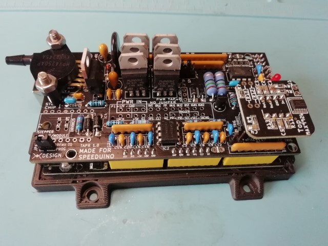
NO2C
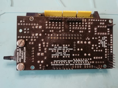 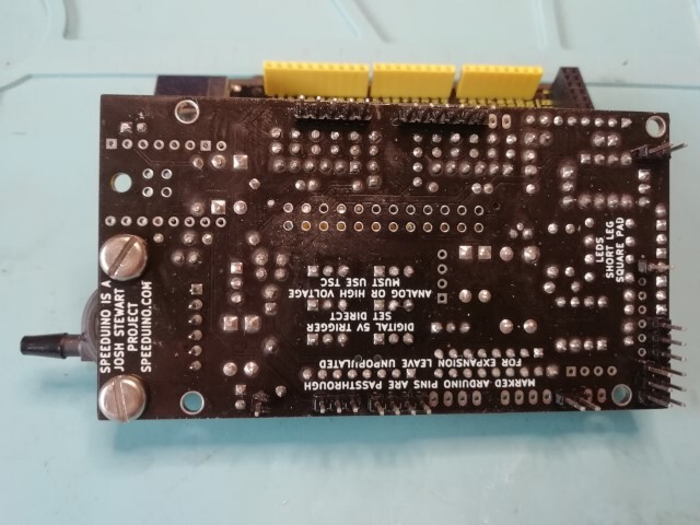
NO2C bottom
|
|
|
MikeR
|
| posted on 17/9/23 at 11:36 PM |
|
|
Check if the connector is actually a pc power supply ATX 24 cable. Means you can buy an extension cable for not much and for you've got the
connector and 6 or 12" pig tail (once you cut the other end off). Saves lots of hassle.
|
|
|
robocog
|
| posted on 18/9/23 at 04:19 PM |
|
|
Unfortunately it is not an ATX PSU connector...it is like one that has been shrunk in the wash
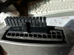 
Mini ATX
Pins are same size as dupont pins!
compared to dupont
(just checked and the male dupont is an OK fit into the female ...infact maybe a slightly tighter fit than the ones in the male plug end that would
get soldered to the board)
They simply look too skinny and not enough surface area to carry any current TBH
I know that the igniter outputs and sensors wont need to pass much current...but in the MS I was using DB37 and inj outputs are using 2 pins each to
share the current
I am thinking of doing the same and using a DB37 to wires direct soldered to the board...and again maybe share a couple of pins for the injectors as
that is something that has never let me down ....yet
The female connectors in comparison with DB37 male pins....
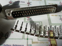 
Female compared to DB37 male
My senses are saying that fitting the supplied plug will come back and bite me ...and be a real pain to remove later without lifting pads or damaging
stuff
Maybe fitting a full size ATX connector via a pigtail is an option....so you may be onto something with the ATX extender idea
BUT I do have a bunch of DB37's here already...will give it some serious thought
Using a DB37 on a pigtail and pinning it to reuse the loom I have is looking favourite
Just a bit shocked at how small and skinny the supplied connector is, maybe it would be fine and I am overthinking it
|
|
|
MikeR
|
| posted on 18/9/23 at 08:12 PM |
|
|
Speeduino v0.4 board used an idc connector on the board. Lots of people questioned this. Josh did a video. It can handle the power, in fact the bit to
worry about is the traces on the board which are much smaller. Speeduino doubles up the injectors to two pins in case you are running batch injection
on a V8 (ie two injectors per channel).
|
|
|


.JPG)