Chris_G
|
| posted on 13/4/04 at 01:56 PM |

|
|
Front Lower Wishbones Bending?
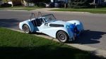
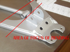
I am actually posting this on behalf of my mate who has a V8 locost. Last year whilst hammering round Castle Coombe he managed to bend the nearside
lower wishbone. Now the thinking was that the car had been built by someone else and the wishbones were of unknown quality so both lower wishbones
were replaced with items purchased from an engineering company up north (can't remmember the name). To help with any potential problems the
wheels/tyres were replaced with 14" lighter items and Yoko 539's and the damper settings were also softened as these were deemed to be set
much too firm. However yesterday after a Blat it was noticed that the offside lower wishbone has now gone the same way (although not quite as bad).
Does anyone have any ideas as to why this should now be happening?
Rescued attachment Nicks wishbone.jpg
|
|
|
|
|
JoelP
|
| posted on 13/4/04 at 02:04 PM |
|
|
i would contact the company that supplied them myself, im sure they will want to see the part themselves. they would probably be as gutted as your
friend.
no idea why it has bent myself, unless they werent designed for v8 use?!
|
|
|
locoboy
|
| posted on 13/4/04 at 02:07 PM |
|
|
probably not the cause but maybe it has "bumped" on full travel and the wall of the tube had been creased on the edge of the hole in the
side panel and therefore allowed it to then bend? Just a guess.
or there is something inherantly wrong with the geometry, ie lengths of bones etc. I would remove the coilover and see if you have free travel to full
bump and full droop, compare to the other side too.
Hope you iron it out cos it cant be much fun knowing its going to do that every time your out in it.
[Edited on 13/4/04 by colmaccoll]
ATB
Locoboy
|
|
|
Alan B
|
| posted on 13/4/04 at 02:13 PM |
|
|
Bottom line...
Uncle Rons "design" loads the lower wishbone in bending more than is healthy....usually everyone gets away with it....
|
|
|
Chris_G
|
| posted on 13/4/04 at 02:42 PM |
|
|
Joel
quote:
unless they werent designed for v8 use?!
These are 'standard' wishbones......Is there such a thing as a V8 Wishbone?
My friend tells me that the Rover V8 doesn't weigh much more than a Pinto?!
colmaccoll
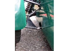
I'm pretty sure there was no bump against the body work, the picture shows the original wishbone which went whilst on track, the one from
yesterday was much less dramatic, but still bent but the paint is still OK, ie no witness marks etc.
Your idea on removing the coilover and checking for free travel is a good one and I will be suggesting that.
It does make you wonder about the geometry now though?! 
|
|
|
derf
|
| posted on 13/4/04 at 02:47 PM |
|
|
I agree with mr meerkat, the lowers arent position perfectly to compensate for the loads, but with the lighter engines, it really isnt a proble, my
guess is that the V8's extra weigh is the contributing factor. Next time you build a set of arms, make them thicker walled, or have a double
tube (2 side by side or on top) for extra strength.
|
|
|
Peteff
|
| posted on 13/4/04 at 04:29 PM |
|
|
Are they cds tube?
The recommended diameter can be bought in 3mm wall thickness and should stand up to anything. I think MK have it. You could invest in some oval DOM
tube which is supposed to be stronger. It looks like the suspension bracket support plate is the weak point, it is a long way back towards the body
and might be somehow levering against the shock mount or weakened by the weld.
yours, Pete
I went into the RSPCA office the other day. It was so small you could hardly swing a cat in there.
|
|
|
marc n
|
| posted on 13/4/04 at 06:28 PM |
|
|
with something with the weight of a v8 upfront i would say that the tube is too small in diameter and is not thick enough wall size, would definately
recommend 30 x 15 x 2mm as a suitable replacement
|
NOTE:This user is registered as a LocostBuilders trader and may offer commercial services to other users
|
Jon Ison
|
| posted on 13/4/04 at 06:47 PM |
|
|
RV8 weighs less than a pinto or thereabouts, maybe weak but i would suspect/check for some stiffness, binding, lack of travel locking up solid ect
too....
|
|
|
Bob C
|
| posted on 13/4/04 at 07:27 PM |
|
|
Very very interesting! I was going to use oval for the lower (just using stock ERW for the upper 'bone). I note MK uses oval on the lowers but
"alongways" rather than up/down so I'm not sure about getting extra beam strength from it, but should be better aerodynamics! I
would not have expected the bend to happen there, I'd have expected it near the shock bottom mounting. And why the back & not the front?
Maybe a fat bloke used it as a step??? Perhaps that long weld has "tempered" he tube up to the bending point? I think I'll use inch
CDS now i've seen that! It's true the RV8 is very light - IIRC the corner weights for the MGBV8 were within 3lbs of the 1800!
Bob C
|
|
|
chrisg
|
| posted on 13/4/04 at 08:00 PM |
|
|
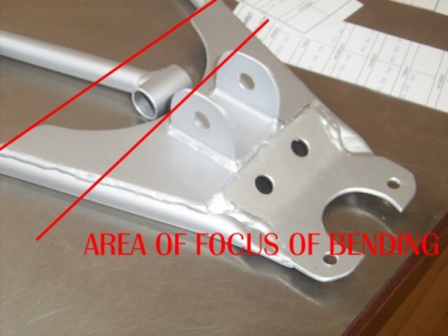
Looking at the pic - that wishbone's not the "book" design is it?
The plates much bigger, and not shaped.
Could be important.
Cheers
Chris
Note to all: I really don't know when to leave well alone. I tried to get clever with the mods, then when they gave me a lifeline to see the
error of my ways, I tried to incite more trouble via u2u. So now I'm banned, never to return again. They should have done it years ago!
|
|
|
Alan B
|
| posted on 13/4/04 at 08:04 PM |
|
|
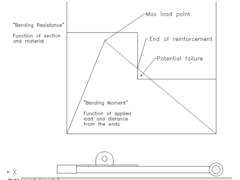
My view of what happened......
Wishbone
|
|
|
Mark Allanson
|
| posted on 13/4/04 at 08:14 PM |
|
|
Alan,
I am with chrig on this one, I think he has hit the nail on the head. The curve of the reinforcement plate will extend the area of maximum bending, an
this will lessen the load on a very specific are of the tube by speading it over a larger area.
I am relying on this as I have a heavy pinto and 19mmx2mm seamless lower tubes!
If you can keep you head, whilst all others around you are losing theirs, you are not fully aware of the situation
|
|
|
Mark Allanson
|
| posted on 13/4/04 at 08:17 PM |
|
|
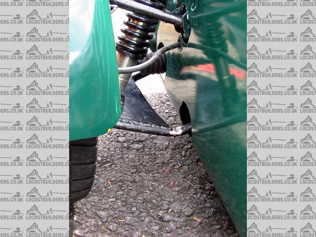
...........on rejoining the thread after posting, I looked at the picture again, the spring on the coil over looks like it is wound right up, there
cannot be much travel or springing action, ALL the load must be on the lower wishbone?
If you can keep you head, whilst all others around you are losing theirs, you are not fully aware of the situation
|
|
|
DavidM
|
| posted on 13/4/04 at 08:54 PM |
|
|
I agree with Mark Allanson. The plate looks bent, as if the suspension has travelled further than the spring would allow. In this case the wishbone
would turn into a see-saw and all the stresses generated would concentrate at that point in the tube where it has bent, exactly as detailed in Alan
B's sketch.
Would suggest hitting a high curb on an apex or similar would do it, or even the same curb several times.
|
|
|
Mark Allanson
|
| posted on 13/4/04 at 09:37 PM |
|
|
What I meant was that the area susceptible to bending is larger with the reinforcement with a curve in it than a straight reinforcement, just like
alanb's diagram
Rescued attachment Wish Bend.jpg
If you can keep you head, whilst all others around you are losing theirs, you are not fully aware of the situation
|
|
|
Chris_G
|
| posted on 13/4/04 at 10:01 PM |
|
|
Guys,
This has obviously rattled a few cages!
To clear some points up.
Our thoughts on the plates being straight edged and not curved were the same, ie with the curve you spread the load a bit more, however the
replacements were exactly as per the book and supplied by a Locost part maunfacturer, not home made jobbies. These have the curved edge and yet the
tube is still bending. You are right in noticing the plate had also 'dished' due to the load from the shocker but again it was found that
the plate used seemed thinner than that suggested by the book and we realised that the shocks were set far too hard. The wheels in use when the
attached picture was taken were also 17" fox alloys which weighed about 20kg each with tyres but as said earlier these have been swapped for
14" jobbies weighing around 15kg.
I think the only way forward in this case is to 'beef-up' the tubes and see what happens!
I'll try and get a picture of the latest wishbone failure for you guys to mull-over!
Chris
|
|
|
Bob C
|
| posted on 13/4/04 at 10:12 PM |
|
|
All good points but still alarming! Al's theory looks plausible but he's had to half the bending strength where the 2mm plate ends to make
it work. On the picture the plate extends a good way towards the chassis. And most folk have 275lb springs on there, plus the dampers wound right up.
Could it be that a lot of us actually have undamped springing supplied by bending wishbones, not the coilover damper units!!
What a good thread! This is where this kind of forum is worth its weight in gold. However did we manage in the olden days before the
internet.......
cheers
Bob C
|
|
|
NS Dev
|
| posted on 13/4/04 at 11:36 PM |
|
|
Is it my imagination or are the front coilovers much more vertical than in the "book"? If the mounting point on the lower wishbone is
correct then is the upper mounting too far outboard? looks to me like the shocker is more upright anyway and this will dramatically increase the
effective spring rate for a given spring fitted. Very heavy spring rate combined with hitting curbs could have done this. Before we all start
worrying, sevens have used this type of wishbone for many years, and other considerably heavier kit cars have used similar designs, so let's not
all criticise until we know what we are doing!
|
|
|
Dale
|
| posted on 14/4/04 at 12:56 AM |
|
|
With the lower arm folded like that it would bring in the outer side of the arm/shock mount making the shock look like it was mounted more
vertically.
I am just at the point of installing rockers for inboard shocks and find all this info great even if my setup is different the same worries carry over
to different parts.
Dale
|
|
|
Rorty
|
| posted on 14/4/04 at 01:19 AM |
|
|
I know what Alan B's talking about and I also take on what Mark Allanson refers to, but I think this particular problem lies elsewhere.
It's of little consequence if the shock bottoms out, so long as the top and bottom shock mounts stay put. I've seen similar cases to this
with poorly built home-made off-road cars where the extreme punishment of jumping and general off-road conditions will soon highlight any
weaknesses.
I reckon the front wishbone pivot is the trouble. It may be seized, in need of lubrication, or the actual wishbone bracket on the chassis may be
off-axis, which combined with a less-than-perfect Metalastic type bush can duplicate the effects of a seized bush.
If the pivot doesen't pivot (properly), then something along the way must bend. Making another new wishbone out of thicker wall tube still may
not cure the problem.
If everything is well designed and works properly, 22.2mm or 25.4mm tube with a wall thickness of 1.6mm should be sufficient. I really do think
Ron's choice of 19mm x 1.6mm is a little optimistic. Far more strength can be obtained by increasing OD rather than wall thickness.
Forget oval and teardrop tube, it's a wank. It may offer increased resistance if you intending doing lots of nose-first landings off a
humped-back bridge, but apart from that, in these circles at least, it's just for poseures.
Cheers, Rorty.
"Faster than a speeding Pullet".
PLEASE DON'T U2U ME IF YOU WANT A QUICK RESPONSE. TRY EMAILING ME INSTEAD!
|
|
|
Alan B
|
| posted on 14/4/04 at 01:43 AM |
|
|
Guys, just to re-iterate my point....I'm only trying to explain why it bent at THAT location rather the circumstances under which it
occured......
What I'm saying graphically is the un re-inforced section is the weakest (obviously) and the the point that it bent was the highest loaded
location of the weakest section.....again pretty obvious.
The real question...which everyone is trying to answer, is what caused that loading to by high enough to cause the bending?
While I don't necessarily agree with Rorty's diagnosis it this case, it is true that this is a common cause of part failure....parts which
should rotate being subjected to bending loads they weren't designed for.....a famous mining accident was found to caused by this phenomenon, a
brake shaft pivot was siezed and was flexing a tensioner rod which should have been pivoting like a rod end...so although the tensile loading on the
brake rod was quite low it had bending loads to deal with which were not designed for and hence failed due to fatigue and several lives were lost.
|
|
|
Chris_G
|
| posted on 14/4/04 at 07:41 AM |
|
|
Just to clear up another point......
NO CURBS WERE HIT IN THE MAKING OF THIS WISHBONE
But seriously, the wishbone was fine when Nick (the car's owner) went out of the pits and he felt it go as he turned through Quarry corner at
Castle Coombe. The car was 2 up at the time but there was no jumping or curb hitting!
I guess the stiffness of pivots is something that needs checking but remember that the one that went this Monday has only been on there for a couple
of months and only done about 50 miles or so since being built!
Chris
|
|
|
britishtrident
|
| posted on 14/4/04 at 07:55 AM |
|
|
The reason why the the wishbone failed where it did is that the end weld to the plate acts as a stress raiser --- a this point the plate weakens
the wishbone more than it strengthens it. The grain structure of the steel at this point due to the heat of welding would also reduce the strength of
the steel at this point. The plate also ends very close to the point of peak bending moment on the lower wishbone -- all of which is not good
design.
The failure probably occured when the suspension hit a minnor bump under braking.
The lower wishbone tube buckled at the corner of the weld to the plate where stress is highest and as a result lost its structural stiffnes and
kinked.
Tiger had to recall wishbones after suffering similar faillures
The book wishbones aren't a good design a better design of lower wishbone is sold by GTS -- on Gts wishbones the reiforcing plate dosent end
in a sharp right angle at the point of max bending moment.
[Edited on 14/4/04 by britishtrident]
[Edited on 14/4/04 by britishtrident]
|
|
|
Bigfoot
|
| posted on 14/4/04 at 08:25 AM |
|
|
I have an RV8 car, and the engine weight is not an issue. Even the vehicle weight should not be a problem, as in a correctly designed wishbone
suspension, with the spring mounted so far out, there is very little of the vehicles weight acting directly on the inner bushes or the lower arm
itself. The main stresses are lateral loads from cornering and braking. It looks a bit flimsy to me, a combination of heavy braking and cornering
would load it up heavily, and as others have said, it is logical that it would bend where the reinforcing plate stops.
Lightweight tubular wishbones are only really suitable when spread further apart at the chassis mount points, making an angle of 90 deg. to each
other at the outer ball joint, the loads are then acting directly along the tube rather than trying to bend it. My front suspension is built quite
heavily, the unsprung weight penalty is not that significant in a road car, and we certainly have more than enough power to push it along.
Sorry for the long winded post.
Cheers
Bigfoot
|
|
|