Sierra
|
| posted on 23/12/14 at 09:25 PM |

|
|
Blacktop supercharge project avon
Good evening fellow kit car builders.
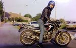
I currently have a tiger avon with a blacktop engine and m45 supercharger.
Over the next few months I want to take on an exciting project to upgrade a few bits including adding a larger m62 supercharger and front mount
intercooler.
Although I'm willing to give most things a go, I have never welded before and this is where I require some assistance.
It's a bit of a long shot but wanted to ask if there's anyone that does some private work, evening/weekends or can weld and is willing to
help me in this project. Or can recommend a garage that can do the work.
The areas where I will need help are
-cutting, extending and welding an inlet plenum that I bought to a different angle, roughly 45 degrees so it allows the charger to sit below.
-make and weld brackets to hold the charger in place
-inlet and outlet for charger, I currently have blank plates that cover the inlet and outlet.
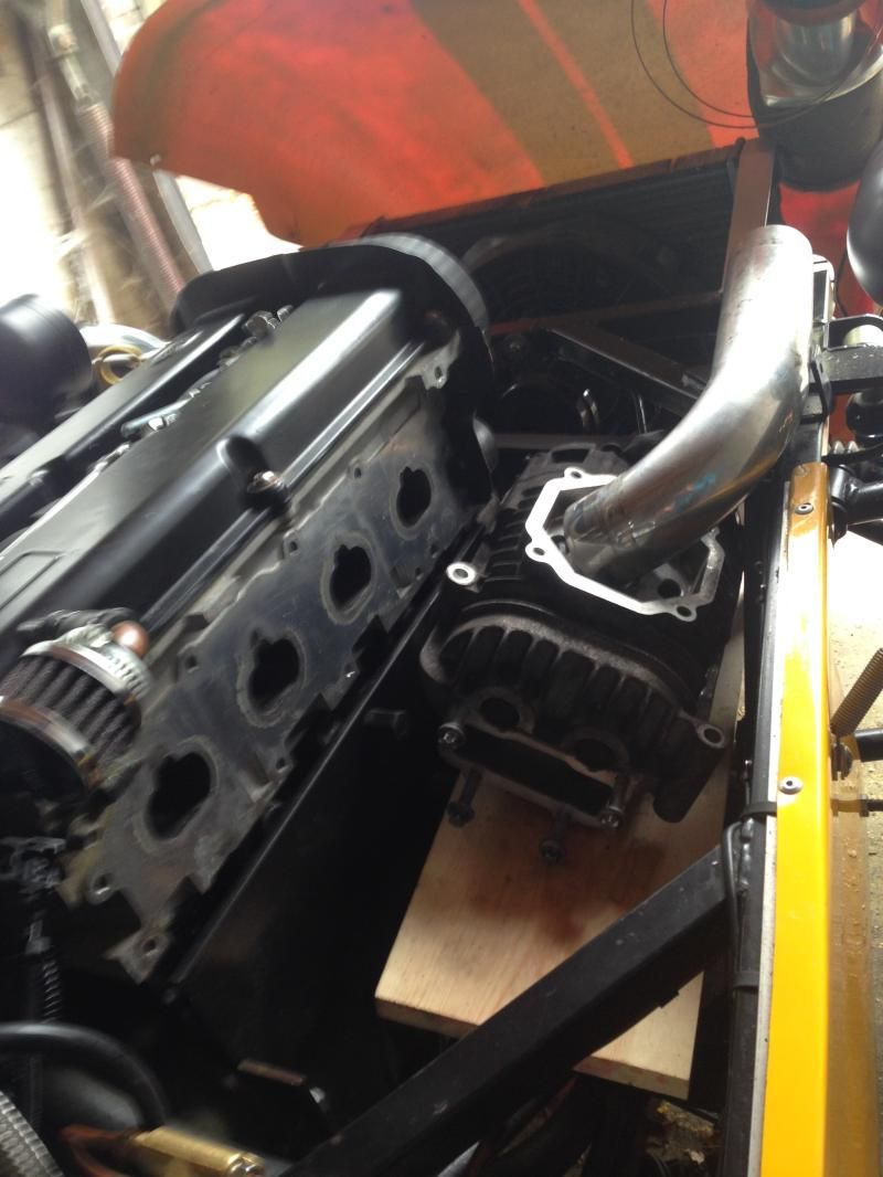
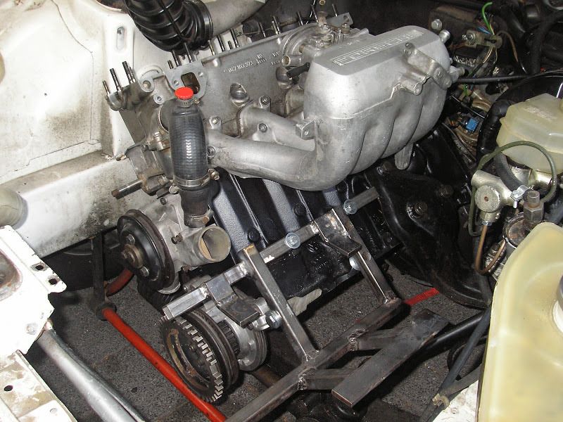
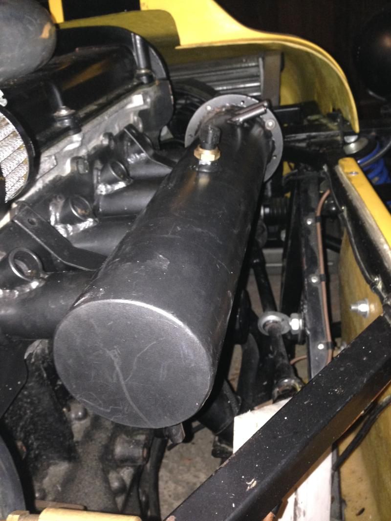
Old setup with m45 bolted straight to custom inlet.
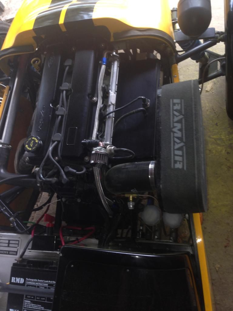
All stripped out
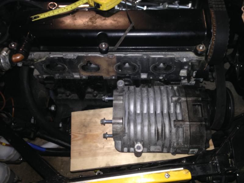
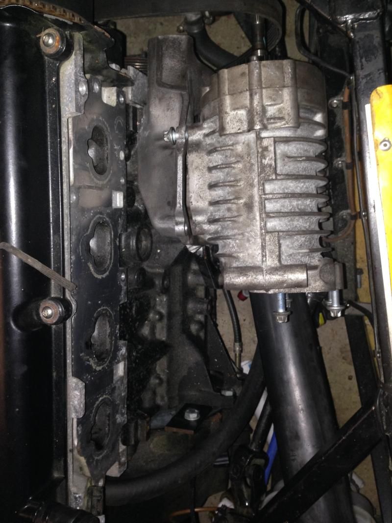
Where I want the m62 to sit (brackets need making)
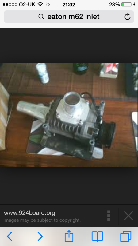
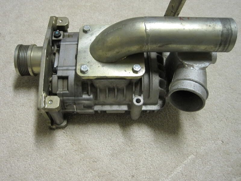
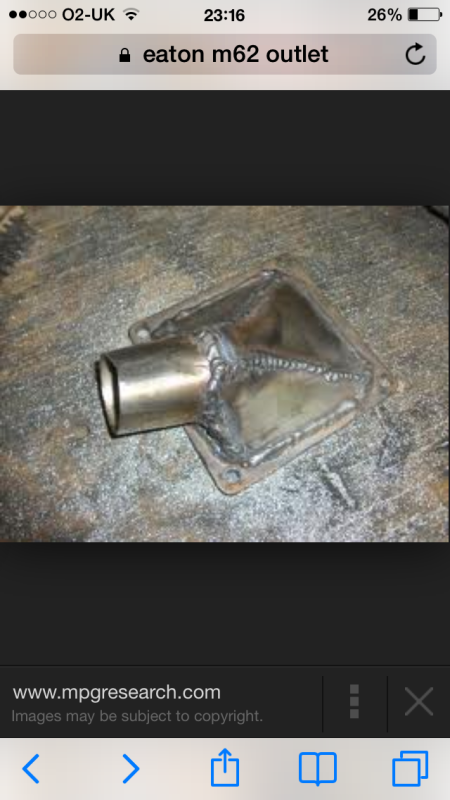
Examples of inlet/outlet that I need
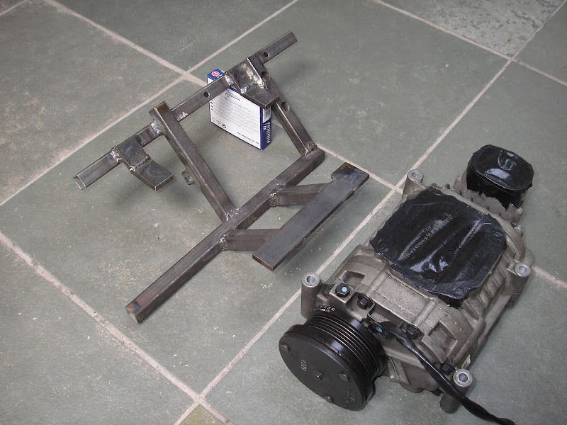
Example of a bracket made to hd the charger
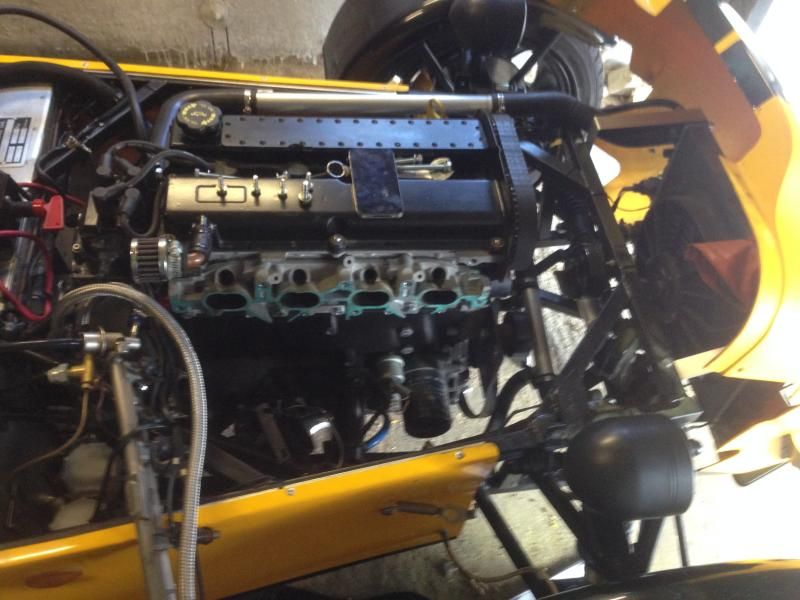
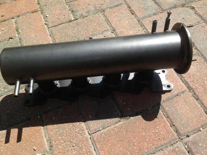
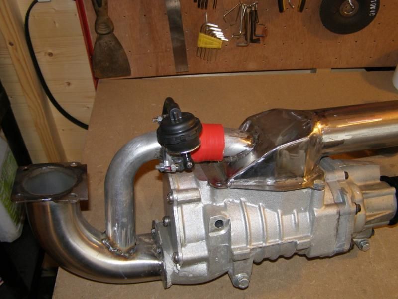
Inlet that I have purchased. (Needs cutting, 4 tubes extended and angled at roughly 45 degrees)
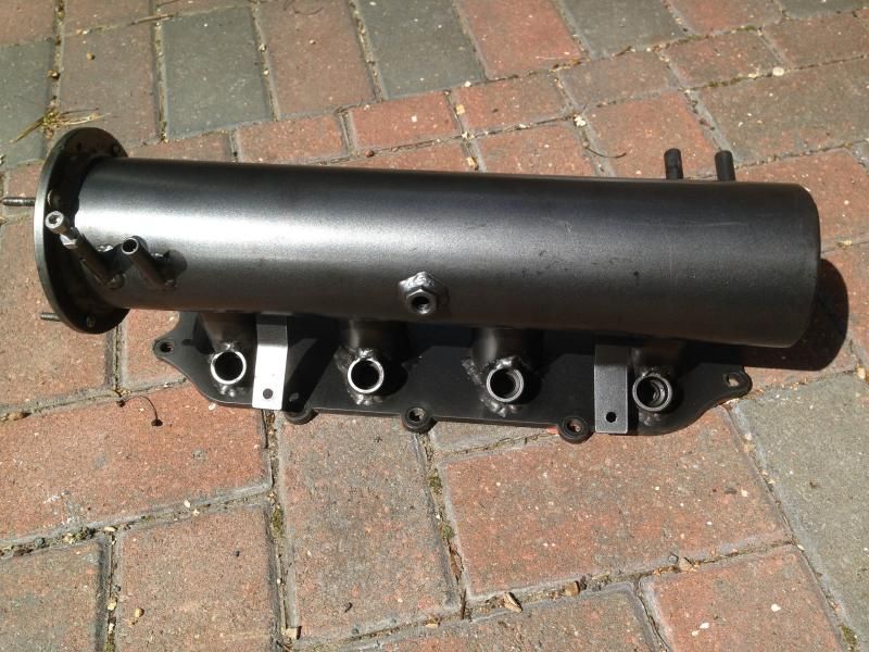
Rough idea of how the inlet should be angled
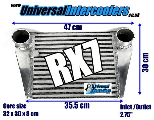
Intercooler that I will purchase
The only other question would be, do I fit the tb to the plenum after the charger and use a recirculating dump valve which is connected back to before
the charger
Or
Fit the tb before the charger like they do on the mx5's. Why do they have the inlet connected to the outlet like that though?
|
|
|
|
|
mark chandler
|
| posted on 23/12/14 at 10:20 PM |
|
|
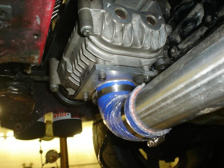
Putting a tube like that on the outlet of the charger will kill power, you need to make up a curved cone leading into the pipe towards the
intercooler, also the charger throws air towards the wide end of the V, so whoever manufactured the earlier photos that would have done better by
putting the tube towards the nose, the last one looks pretty good.
That aside if you fit up all the parts I can have a go at welding it together for you, I am about 1 hour away down the M4.
Regards Mark
[Edited on 23/12/14 by mark chandler]
|
|
|
Sierra
|
| posted on 23/12/14 at 11:18 PM |
|
|
Many thanks for your advice and offer. I'll see if I can get bits together but I'm very new to this so might need help
So something like this would be better?
|
|
|
mark chandler
|
| posted on 23/12/14 at 11:50 PM |
|
|
That's ugly but better than the flat plate/tube affairs, imagine how the air would flow so if you provided a nice curve from vertical to
horizontal then you are onto a winner so turn the air not bounce it off a 45 degree plate, use the side profile of the mandrel bend sculptured into
the 3" pipe.
Also remember the V is the exhaust port, not the square plate which is designed for mounting stuff easily.
Regards Mark
|
|
|
flak monkey
|
| posted on 24/12/14 at 09:15 PM |
|
|
Shouldn't be that difficult to make a fabricated outlet for the blower. Maybe take half a day to do something to suit.
A log type inlet would be easy too.
Ref your question about the inlet connected to the outlet, see that black valve in the pipe? It's a BOV that prevents boost spikes when the
throttle plate is closed. You only need that if the throttle plates are AFTER the blower. If the throttle body is BEFORE the blower you don't
need one.
[Edited on 24/12/14 by flak monkey]
Sera
http://www.motosera.com
|
|
|
coozer
|
| posted on 24/12/14 at 09:19 PM |
|
|
I have one of them intercooler with the little angle bracket cut off. Apart from that brand new never used with the pipes and clips.
Want it?
1972 V8 Jago
1980 Z750
|
|
|
Sierra
|
| posted on 24/12/14 at 09:25 PM |
|
|
I thought it was for that reason but got a bit confused as I could see the tb before the blower. Turns out they are running 2 tbs which is why they
have the dv. Although I was told that the vdw should go after the intercooler and before the tb which it seems isint the case with that one.
Are these things that you can fabricate then or know of someone that can?
quote:
Originally posted by flak monkey
Shouldn't be that difficult to make a fabricated outlet for the blower. Maybe take half a day to do something to suit.
A log type inlet would be easy too.
Ref your question about the inlet connected to the outlet, see that black valve in the pipe? It's a BOV that prevents boost spikes when the
throttle plate is closed. You only need that if the throttle plates are AFTER the blower. If the throttle body is BEFORE the blower you don't
need one.
[Edited on 24/12/14 by flak monkey]
|
|
|
flak monkey
|
| posted on 24/12/14 at 09:31 PM |
|
|
If you can give me reasonable sketches of what you need I can look at the fabrication work for you if you need someone to do it for you.
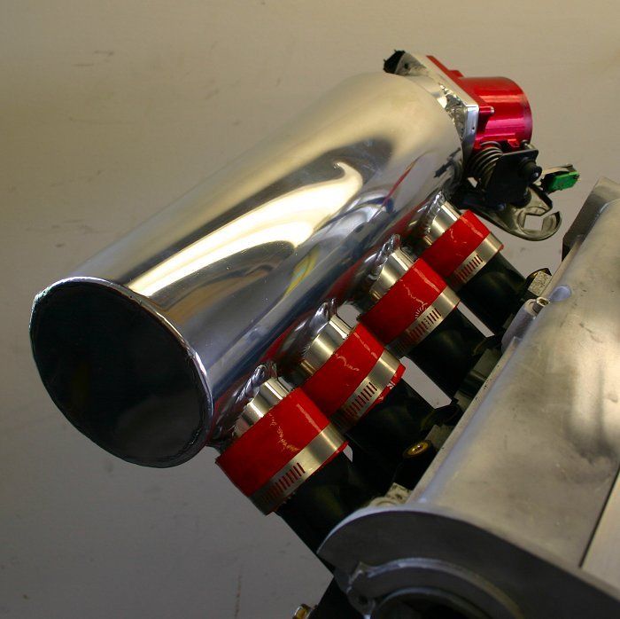
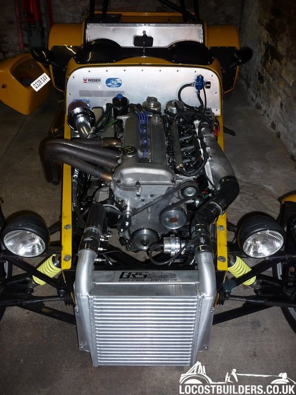
Good practice puts the BOV as close to the throttle plates as possible, so yes, normally after the intercooler. This was my set up.
Sera
http://www.motosera.com
|
|
|
Sierra
|
| posted on 24/12/14 at 09:39 PM |
|
|
Wow that looks very nice, what setup is that and figures produced
|
|
|
flak monkey
|
| posted on 24/12/14 at 09:48 PM |
|
|
2 litre Duratec - the build of it is in the stickies at the top of this section
Rotrex blower, 290bhp/240lbft @ 9psi - engine was built to take more. Simple change of pulley would allow peak boost of over 15psi.

[Edited on 24/12/14 by flak monkey]
Sera
http://www.motosera.com
|
|
|
jeffw
|
| posted on 24/12/14 at 09:51 PM |
|
|
There was probable another 100-150BHP in Flak's engine. If you think mine is running 1.2 Bar or nigh on twice the boost as Flak's setup
using the same supercharger.
[Edited on 24/12/14 by jeffw]
|
|
|
Sierra
|
| posted on 24/12/14 at 10:10 PM |
|
|
Very impressive setups, both of yours.
I would love a rotrex but really don't have the money for one. I'm trying to re build mine at the best price possible, plus it'll be
a bit of fun 
|
|
|
Sierra
|
| posted on 24/12/14 at 10:43 PM |
|
|
I'll try and get some rough sketches together with measurements. I take it your DVD wasn't recirculating or is it just not visible in the
pic?
quote:
Originally posted by flak monkey
2 litre Duratec - the build of it is in the stickies at the top of this section
Rotrex blower, 290bhp/240lbft @ 9psi - engine was built to take more. Simple change of pulley would allow peak boost of over 15psi.
[Edited on 24/12/14 by flak monkey]
|
|
|
mark chandler
|
| posted on 24/12/14 at 10:50 PM |
|
|
The eaton will not match those figures, it's a displacement charger so not as efficient, even with the same boost level it will be dragging HP
off the front pulley to spin it.
Saying that my DB7 has a M90, I like it 3.2 litre pushing 385bhp with over 300lb/ft above 2000rpm peaking to 370 lb/ft, not great figures per cc
but older technology running around 12 psi.
 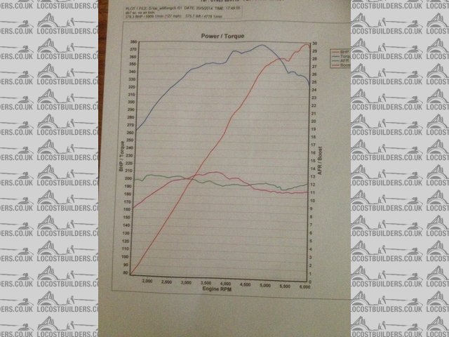
power run
Makes a great noise
http://youtu.be/v4OfO40D72w
[Edited on 24/12/14 by mark chandler]
|
|
|
Sierra
|
| posted on 24/12/14 at 11:04 PM |
|
|
Oh yes definitely not expecting figures anywhere near that. Just want to upgrade so I'm not pushing the charger to its limits like I would be
with the m45 and this time have cooling with the intercooler.
Don't have a clue what the figures will be but that's part of the fun
|
|
|
jeffw
|
| posted on 25/12/14 at 08:16 AM |
|
|
quote:
Originally posted by Sierra
I'll try and get some rough sketches together with measurements. I take it your DVD wasn't recirculating or is it just not visible in the
pic?
The DV is between the intercooler and the inlet (the shiny thing in front of the engine). Mine is off the plenum itself. You can do this with recirc
valves but it is probable better to have a 'To Air' DV as it will keep the inlet temps down a bit more than a recirc one.
|
|
|
mark chandler
|
| posted on 25/12/14 at 10:19 AM |
|
|
You do not have a DV with an eaton, just the bypass valve as during low throttle openings it does not pressure the system.
|
|
|
Sierra
|
| posted on 2/1/15 at 10:48 PM |
|
|
I had a spare but of time today so I test fitted the inlet that I bought a whole ago, just to see how it fits.
As you can see it is horizontal from the block so sits very low down. For me to be able to fit the charger underneath I need the plenum to sit much
higher up.
Do you guys think it would be best to cut the 4 ports straight just after the injector holes, then get someone to weld extended tubes at a 45 degree
angle. Or. Buy a new different inlet or have one made?
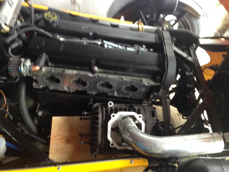
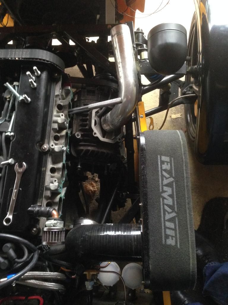
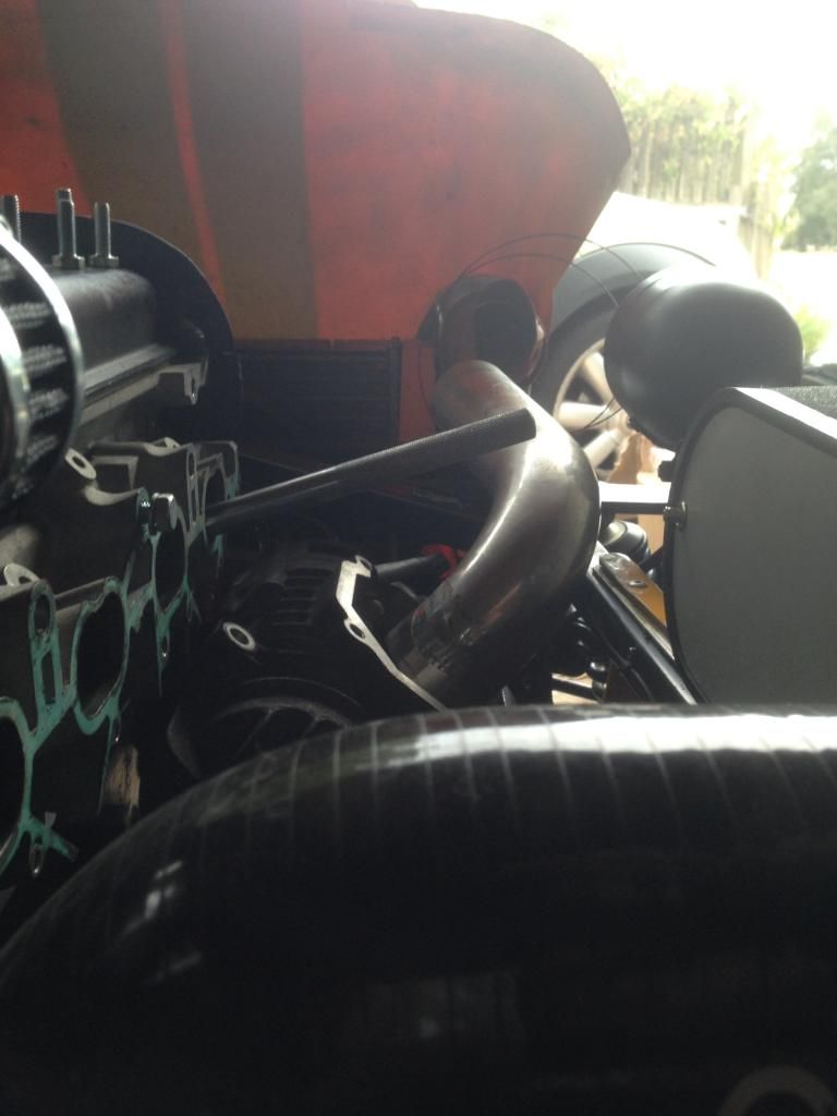
I also played with different positions for the charger again.
Outlet facing down
Charger side on
|
|
|
jwhatley
|
| posted on 2/1/15 at 11:16 PM |
|
|
Good to see you are still fighting on with this project.
In my experience with these chargers as mentioned before, they are a pretty good heat pump, so keeping them and the charge air cool is a must.
I wouldn't use a BOV on this type of charger, dumping the boost to atmosphere sounds cool to some people, but the problem with doing this with
these chargers is the risk of belt slippage. I found that when using a BOV as a trial when the throttle was re opened and the BOV closed the boost
spike cause the belt to slip due to compressor stall. Not an issue on the likes of rotrex or vortec chargers as the puppy diameter is approx 25-30mm
larger.
I would suggest using a diverter/recirc valve and the TB's post charger. Have ithe diverter connected from the plenum back to the inlet of the
charger. I say this purely for cooling of the charger and the charge air. With the TB's closed or at partial throttle when driving you want to
keep the air flow running through the charger to cool it internally, using the intercooler also to cool the air and then port it back to the charger
inlet to be re used. If you have an efficient I/C this will work really well.
John
|
|
|
Sierra
|
| posted on 2/1/15 at 11:33 PM |
|
|
Thanks for the info. I'm a bit confused when you say the diverter/ recirc at the plenum, do you mean after the tb.
I was going to fit the tb to the plenum so after charger and fit the recirc after the intercooler but before the tb. Recirc connected back to charger
inlet (between air filter and charger)
|
|
|
jwhatley
|
| posted on 3/1/15 at 06:48 AM |
|
|
Hi,
Yes that's what I meant. I don't know why but I seemed to think you were going to use ITB's.
|
|
|
Sierra
|
| posted on 7/1/15 at 11:05 PM |
|
|
Just a quick question guys.
What way does the crank pulley turn?
Just came to me if I will be turning the charger the correct way. The m62 needs to turn anti clockwise.
|
|
|
flak monkey
|
| posted on 8/1/15 at 07:12 AM |
|
|
All engines, with a few exceptions of Hondas and early Citroens, all turn clockwise viewed on the front of the crank shaft (i.e. looking at the front
of the engine). Or CCW viewed from the flywheel end.
Sera
http://www.motosera.com
|
|
|
Sierra
|
| posted on 8/1/15 at 09:58 AM |
|
|
Many thanks. Sorry I was having a bit of a blonde moment, when putting the rotors back in the casing I put them the wrong way making the charger ccw.
Now it's all correct it's cw like the engine
|
|
|
Sierra
|
| posted on 8/1/15 at 12:51 PM |
|
|
Does anyone know what metal the griffin inlet plenum is made of? And where I could get inlet ports to extend the standard ones?
|
|
|