RazMan
|
| posted on 8/12/05 at 11:59 PM |

|
|
Sierra Stalk Diagram?
I've just spent half an hour of headscratching with my Sierra stalks and a wiring diagram - nothing made sense.
Then I realised I was looking at a Mondeo diagram!! (well it's late isn't it)
Has anyone got a scan of the Haynes manual page or similar of a Sierra stalks diagram?

Cheers,
Raz
When thinking outside the box doesn't work any more, it's time to build a new box
|
|
|
|
|
k33ts
|
| posted on 9/12/05 at 12:02 AM |
|
|
i got the indicator side and lights if thats anygood
|
|
|
k33ts
|
| posted on 9/12/05 at 12:21 AM |
|
|
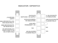
this is tigers diagram should be ok.jpg)
|
|
|
k33ts
|
| posted on 9/12/05 at 12:25 AM |
|
|
u2u your email and ill send you a bigger 1 if you want
|
|
|
Peteff
|
| posted on 9/12/05 at 12:34 AM |
|
|
What year Sierra?
They used different systems, 3 altogether I think.
yours, Pete
I went into the RSPCA office the other day. It was so small you could hardly swing a cat in there.
|
|
|
RazMan
|
| posted on 9/12/05 at 09:29 AM |
|
|
Thanks for the scan k33ts. It is rather fuzzy but (from what I can make out) I don't think it would help me anyway as it only details the
Tiger part of the circuit - I need the pin-outs of the stalk switches so that I can splice them into my own loom.
Pete, I am not sure what year - there are two assemblies with two connectors on each:
Left: Single stalk - Dip & Main & indicators
Right: Two stalks - Lights on + 3 position wiper with washer button on the end.
Does that help?
Cheers,
Raz
When thinking outside the box doesn't work any more, it's time to build a new box
|
|
|
flyingkiwi
|
| posted on 9/12/05 at 01:19 PM |
|
|
I'm at the same head scratching stage myself.
try this pdf
http://auto.novgorod.ru/tech/haynes-ford-sierra/0903-wd.pdf
Its got the wiring diagrams from the haynes manual on it from all three types.
I spent 3 lunch breaks scratching my head over it until I realised I was using the wrong year, its amayzing what differences there are. You should be
able to trace back the switches on the diagram and compare the colours of the wires you've got. Word of warnging though. A couple of switched
earth wires go from the headlight switch on the right to the indicator switch on the left, nearly came unstuck when I got snip happy. Also make sure
the right connectors are on the right side as the plugs are interchangeable. Found that out yesterday!
[Edited on 9-1212-0505 by flyingkiwi]
It Runs!!!!! Bring on the SVA!
|
|
|
RazMan
|
| posted on 9/12/05 at 06:11 PM |
|
|
I know my Russian is a bit rusty  but that link appears to be a blank page but that link appears to be a blank page 
*edit* found it here
http://faq.ford77.ru/pdf/sierra/0903-wd.pdf
[Edited on 9-12-05 by RazMan]
Cheers,
Raz
When thinking outside the box doesn't work any more, it's time to build a new box
|
|
|
rusty nuts
|
| posted on 9/12/05 at 06:57 PM |
|
|
If you look on the switch there is a part number , some Sierra switch used an earth connection to operate I think the headlight dip relay and some
used a positive feed , another had the horn button on the end of the stalk. Part number may help get the correct wiring diagram. I found the Haynes
manual not very helpful I even got the pages blown up to poster size and that did'nt help .
|
|
|
RazMan
|
| posted on 9/12/05 at 10:51 PM |
|
|
I think my switches must be 1987-1989 models judging by the diagram.
I have to agree with Rusty - the diagrams seem needlessly complicated because they have the whole car's diagram whereas I just need the pinouts
for the switches so that I can splice them into my semi-complete (and simple) loom.
Looking at the switch there is indeed a part number but how does that relate to any of the diagrams? They only show the component reference number
which is referenced by the appropriate 'map' list.
I think I should be able to sort out the connections from the pdf diagrams. I will try to simplify and post a Blue Peter version soon to help the
electrically challenged builders like me.
Cheers,
Raz
When thinking outside the box doesn't work any more, it's time to build a new box
|
|
|
Peteff
|
| posted on 10/12/05 at 09:22 AM |
|
|
Brown (15) is earth on Ford looms, don't put power through it as you have it as permanent +ve not -ve. Red is permanent live. The brown/yellow
and brown/white are earths from the lighting relays, don't put power directly through them either as they are only feeble contacts and will burn
out quickly. The brown/black carries the earth from the left to the right side.
[Edited on 10/12/05 by Peteff]
yours, Pete
I went into the RSPCA office the other day. It was so small you could hardly swing a cat in there.
|
|
|
RazMan
|
| posted on 10/12/05 at 10:27 AM |
|
|
Thanks for the tips Pete 
I have revised the dwgs.
 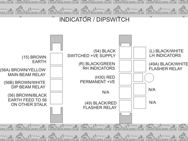
Rescued attachment Sierra switches Diagram1.jpg
Cheers,
Raz
When thinking outside the box doesn't work any more, it's time to build a new box
|
|
|
RazMan
|
| posted on 10/12/05 at 10:31 AM |
|
|
and deleted the old ones to save any confusion
 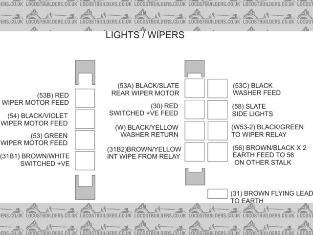
Rescued attachment Sierra switches Diagram2.jpg
Cheers,
Raz
When thinking outside the box doesn't work any more, it's time to build a new box
|
|
|
Bob C
|
| posted on 10/12/05 at 09:44 PM |
|
|
Razman that is gold dust
Thanks
Bob
|
|
|
Peteff
|
| posted on 11/12/05 at 12:11 PM |
|
|
As a rule Ford use Black/ stripe as switched live, Red is permanent live, Brown/ stripe is earthing something. The thick Black/Yellow wire from the
ignition supplies all switched lives, Black included via a busbar or spliced wires and the Red runs the permanent lives in the same way, therefore if
you connect a red or black to a brown it's a dead short if there's nothing in between. There was a thread about it years ago but it seems
to have disappeared.
yours, Pete
I went into the RSPCA office the other day. It was so small you could hardly swing a cat in there.
|
|
|
tks
|
| posted on 11/12/05 at 05:05 PM |
|
|
i made my own diagram..
sow i know exactly wich wire connects to wich in wich position of the switch...
think its in my photo dia gram
else u2u me..
Tks
The above comments are always meant to be from the above persons perspective.
|
|
|


.jpg)