Bob C
|
| posted on 7/2/06 at 01:25 PM |

|
|
Steve - another thread reminded me of this - did you get it working?
Bob
|
|
|
|
|
smart51
|
| posted on 9/2/06 at 07:57 AM |
|
|
How about this one? I think I'll try it at the week end.
What have people done for conenctors into the main loom?
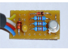 
Rescued attachment exup.GIF
|
|
|
Bob C
|
| posted on 9/2/06 at 10:28 AM |
|
|
Looks really neat smart51.
You could solder direct to the loom or put a 4way connector pair in for easy removal in case of failure - your choice.
One thing I've done in the past with small circuits like this is to 'pot' them by covering all over in hot melt glue. Easy to do but
to all practical purposes irreversible - so do it AFTER you've got it working! Trouble with vero is that the copper strips corrode in an engine
bay & after a few years the circuit would stop working otherwise. This circuit is so small and light it can be just taped to the loom if
it's 'potted' as described.
Bob
PS points to watch - you've used a tantalum cap - be SURE it's polarised correctly or it'll go pop. Also - is that a 2N222? whatever
the can is probably electrically connected to the transistor collector so watch it for shorting to things (eg resistor leads, or the car chassis) on
the top side of the circuit
[Edited on 9/2/06 by Bob C]
|
|
|
smart51
|
| posted on 9/2/06 at 11:07 AM |
|
|
I have got a potting box ready for the circuit once it is tested. I'd rather connect to the existing plug than cut it off and wire in diectly.
I'll have to give it some thought.
|
|
|
Bob C
|
| posted on 9/2/06 at 01:15 PM |
|
|
sure if you have plug, socket & bike loom that's the way to go.
Bob
|
|
|
smart51
|
| posted on 13/2/06 at 02:11 PM |
|
|
I tried the circuit and it works upto 10,000 RPM during acceleration and upto 7500 RPM steady speed. Above this I get the rev needle error code
thing. The circuit is correct, with correct value components and no mis-soldering.
Has anyone got this circuit to work properly?
Also, the zenner diode gets quite hot and I've used a 1.3W diode as maplin ran out of 0.5W ones.
|
|
|
jimgiblett
|
| posted on 14/2/06 at 12:33 PM |
|
|
I've only had the chance to test mine on startup and idle with a few blips on the throttle. Mines an FI motor so I dont get the tacho tango
just the error codes.
When you say the zender gets hot is this a fire risk as I have mine tucked away where it isnt easily accessible?
Rgds
Jim
[Edited on 14/2/06 by jimgiblett]
|
|
|
smart51
|
| posted on 14/2/06 at 02:13 PM |
|
|
The zenner gets hot to the touch and the plastic box it is in gets quite warm. I did 10 - 15 miles to try it out and there was no fire.
|
|
|
Bob C
|
| posted on 14/2/06 at 05:19 PM |
|
|
Hmmm - interesting. Are you sure you used 47kilo-ohm resistors smart51 - if you did it shouldn't be possible to put enough watts into the zener
to warm it:
12V on bl/red to 5V on the zener through 47kohm is about 150micro-amps and the zeners are specced at 5milliamps.
Check for for shorts with a meter - you can get whisker small filaments of copper left when you do a veroboard like this.
If the circuit's right & the zener's getting hot it means the circuit in the CDI unit must be using the pot's resistance, which
would be a bit of an arse to say the least. Jim, you're gonna have to take another look at yours I think! It'll be at least a month before
mine's going & I don't have a silencer yet so I might not be very popular doing 10krevs tests...!!!!
Cheers
Bob
PS - Ta for the heads up Jim!
|
|
|
Bob C
|
| posted on 14/2/06 at 05:24 PM |
|
|
Smart - looking at your resistors I get blue red orange brown which could be 52k or something else (I always check with a ohmmeter to be sure) - can
you measure the resistance of the top resistor?
cheers
BOb
|
|
|
smart51
|
| posted on 14/2/06 at 06:04 PM |
|
|
Yeah. I got the resistors out of a resistor book. the numbers are printed below the pack of resistors. I am allways using the wrong ones. I have
since replaced them with 47K. I have done a full multimeter check on all the components and from each track to each adjacent track. No shorts.
Max power in the Zenner should be 430 uW at an alternator voltage of 13.8V. Not enough to get warm. Perhaps I should take it out and have another
look.
|
|
|
smart51
|
| posted on 17/2/06 at 10:54 AM |
|
|
I have measured my circuit and it is all OK. I measured various voltages with the ignition on and found some strange results. The motor input to the
plain diode was switching on and off rapidly, enough to give a 7.5V AC and 3.5V DC reading. The other motor input was hovering around 0.7V, enough to
leak current out of the cap. I guess that the cap voltage is not holding steady enough and the ECU is trying to maintain EXUP position by nudjing the
motor forwards all the time. This behaviour is not seen when connected to a proper EXUP servo.
Has anyone got this circuit to work properly?
|
|
|
Bob C
|
| posted on 17/2/06 at 11:56 AM |
|
|
OK if the 2nd motor output is hoveriing round 0.7V that's enough to turn on the transistor - solution would be to include a forward biased diode
in the transistor base circuit - do you want to try that smart51?
I'm surprised at the 0.7V thing. The circuit was designed assuming a very simple motor drive/ position control system. I wonder if they've
used an audio power amp chip to drive the motor - that would explain it! & it wouldn't be a bad idea either - integrated driver with short
circuit protection costing peanuts.
cheers
Bob
|
|
|
highspeeddirt
|
| posted on 17/2/06 at 04:48 PM |
|
|
I am still wiring the car at the moment so I've not yet built/tried the circuit. It will be a pity if it doesn't work as that exup motor
seems heavier every time I look at it. 
Steve
|
|
|
smart51
|
| posted on 17/2/06 at 08:27 PM |
|
|
I fitted a zenner into the base of the transistor, as well as the resistor. Both motor inputs bounce up and down. It's as if the circuit
reacts to fast and the ECU is saying up a bit, oops too far, down a bit, oh, too far, up a bit...
I'm tempted to give it up as a bad job. The EXUP isn't that heavy campared to a whole car.
Has someone got a bette circuit?
|
|
|
Bob C
|
| posted on 17/2/06 at 08:58 PM |
|
|
Thats a reasonably accurate description of how negative feedback in servos works......
With the extra 'turn on' voltage on the transistor do you still get the error code at high revs? Is the zener still getting hot?
If the circuit is reacting too fast for the controller, increasing the size of the capacitor will fix that.
There's another circuit on biketransplantcentral (search google for that) which uses a digital potentiometer chip + timer + some logic.
- which is why I thought a much simpler circuit would do the job & made one which Jim tried & it fixed it for him (!).
Shame it's not worked so well for you yet smart51 - It would be nice if you could persevere for the sake of getting a good solution for the R1
engined community, but I can understand if you don't want to spend too much time on something relatively new & untried.
All the best
Bob
|
|
|
jimgiblett
|
| posted on 18/2/06 at 12:11 AM |
|
|
My diagnostic codes have certainly gone at start up and a few blips of the throttle all seems fine. But I am yet to give it a good thrashing like
Smart51 has. So watch this space.
- Jim
|
|
|
smart51
|
| posted on 18/2/06 at 06:24 PM |
|
|
I replaced the 1uF cap with 4.7, 10, 47 and 100uF before the "bouncing" came down to a reasonable level. It works at all engine speeds
and road speeds now, with over 100 miles of testing today. The zenner doesn't even get hot. the only problem is that the tacho needle
bouncing now happens with the ignition on but the engine off. I didn't check the tacho needle with the other values. I might experiment
further another day. The zenner doesn't even get hot. the only problem is that the tacho needle
bouncing now happens with the ignition on but the engine off. I didn't check the tacho needle with the other values. I might experiment
further another day.
|
|
|
jimgiblett
|
| posted on 18/2/06 at 07:21 PM |
|
|
If you have a bouncing tacho when the ignition is on but the engine not running you are in the same position as if you had just spliced the exup wires
together. That was the set up I had on my old 2000 R1.
Cheers
- Jim
|
|
|
Bob C
|
| posted on 18/2/06 at 08:28 PM |
|
|
The ignition module continually correcting the capacitor voltage is really not a problem - like I said - that's how servos work! I don't
know what the exup servo system reacts like, but if the CDI module is expecting it to reach its setpoint in 1/2s or so - a 100uf charged thru 47k is
going to take 10 times that, so that would explain the "tacho tango" on startup - the circuit is behaving like a really slow EXUP servo
& the CDI thinks it's goosed when it does its power up tests. So I'd back off on the microfarads until the powerup selftests pass.
cheers
Bob
PS shame this ain't the best way to debug circuits... it's so much easier 'hands on' . To be honest I was rather surprised
when Jim said it worked 'out of the box' - I expected this kind of 'honing' to be required!
|
|
|
smart51
|
| posted on 18/2/06 at 08:35 PM |
|
|
Which wires do you splice together to stop the tacho bounce when the engine is running? It might give me an idea how to fix the circuit.
|
|
|
jimgiblett
|
| posted on 18/2/06 at 10:42 PM |
|
|
IIRC thr black / Red and the White / Red on the 5XV motor. Never had any "tacho tango" other than on ignition and engine not running.
- Jim
|
|
|
stevebubs
|
| posted on 19/2/06 at 01:47 AM |
|
|
Here's an old old link from the early days of BECs....
http://biketransplant.tripod.com/exup_replacement.htm
[Edited on 19/2/06 by stevebubs]
|
|
|
smart51
|
| posted on 20/2/06 at 08:29 PM |
|
|
10 uF cap fitted and tested. No problems with the engine off or on at any engine speed and any road speed. Next I'll try it without the extra
zenner in the base of the transistor. At last.
|
|
|
Bob C
|
| posted on 21/2/06 at 12:42 PM |
|
|
Weyhey - at last - I'd leave the extra diode in, it's not doing any harm.
I'll edit the circuit diagram in the 1st post to include your findings. I'll just put another 1n4148 forward biased in the transistor base
& change the C to 10mikes
cheers
Bob
PS OK I'll edit it later when I'm at home....
[Edited on 21/2/06 by Bob C]
|
|
|