flak monkey
|
| posted on 21/1/06 at 06:58 PM |

|
|
Broke a rod end today
Not me personally, but someone else test driving a car.
Went to Bruntingthorpe aerodrome/test track with our FSAE car. Great fun 
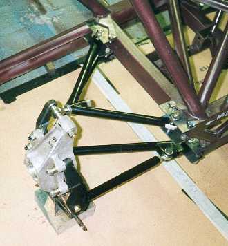
At the end of the day (thankfully) one of the suspension rose joints broke. The threaded shank (male rod end) broke clean through.
Located on the top wishbone of the rear suspension, a single M8 rod end.
Now the car weighs about 300kg with a driver (conservative estimate). SUrely it should not have broken? It broke whilst cornering hard. It was screwed
into an aluminium block at the hub end of the upper rear wishbone. Surely the thread should have pulled out before the rod end broke!
They werent cheap ones (Aurora Bearings)
Any ideas? Or just a duff rose joint?
David
Sera
http://www.motosera.com
|
|
|
|
|
rayward
|
| posted on 21/1/06 at 07:08 PM |
|
|
M8 seems a bit smll to me, would have thought m12 was more suitable?
Ray
|
|
|
Peteff
|
| posted on 21/1/06 at 07:09 PM |
|
|
8mm is a bit puny...,
If it's screwed into the block and locknutted the thread should survive anything you throw at it. The bit sticking out will be at the mercy of
various forces, acceleration and deceleration as well as up and down movement and pulling and pushing by the lateral force on the tyre. Which way on
is the bearing end?
yours, Pete
I went into the RSPCA office the other day. It was so small you could hardly swing a cat in there.
|
|
|
flak monkey
|
| posted on 21/1/06 at 07:12 PM |
|
|
Was screwed into the block and locknutted. Broke off between the locknut and the block.
Mounted so the bolt passes through the rod end vertically.
I would have thought M8 to be sufficient...Rod end are generally very high tensile. With the max shear load being about 0.6 of the tensile load.
David
Sera
http://www.motosera.com
|
|
|
Jon Ison
|
| posted on 21/1/06 at 07:18 PM |
|
|
left hand side upper wishbone by any chance ?
Ive just gone up from M10 too M12 in this position, M10 onto chassis.
|
|
|
britishtrident
|
| posted on 21/1/06 at 07:21 PM |
|
|
If its between the nut and the block it gets shear and tensile -- 8mm is puny especially if there is a bending moment as well.
10 or 12 is nearer the mark --- Normal metric threads are relative coarse which can be a problem --- working in old money I always used 7/16"
unf for the suspension.
|
|
|
flak monkey
|
| posted on 21/1/06 at 07:22 PM |
|
|
quote:
Originally posted by Jon Ison
left hand side upper wishbone by any chance ?
Ive just gone up from M10 too M12 in this position, M10 onto chassis.
.
Yes thats the position...
How much does your car weigh Jon?
Also bear in mind that FSAE cars are raced on a go-kart circuit, the cornering speed isnt that high...30mph max... more than that and you are sideways
or understeering (crap suspension geometry)
David
Sera
http://www.motosera.com
|
|
|
Jon Ison
|
| posted on 21/1/06 at 07:41 PM |
|
|
With me on board 580 kgs, class minimum, the upper top wishbone outer joint on any cars that sees a clockwise track takes one hell of a
pounding........
Several on here whom Ive met at various meetings ect will tell you the 1st thing i do is grab there "rod" end or grab there
"bush" and show them in most cases some free play, on the 1st GT1 which was on bush's it was changed before any track excursion,
since going onto rod ends i work on 3 races/track days and sling it no matter how it feels/looks bit like doing pm's.
That is the one suspension joint that gets some real hammer.
Anyone reading this who as dome track days in there car pop out and waddle your bush, i will be shocked if the one we are talking about doesn't
have some free play.
Be careful out there.
|
|
|
flak monkey
|
| posted on 21/1/06 at 07:52 PM |
|
|
So your car is almost twice the weight of ours at 300kg. You probably also corner at a fair few knots more than us too, and so will put higher loads
through the joints, probably over twice what we acheive, so I am not suprised you would fit 10mm or bigger joints.
The car has probably covered no more than 50 track miles before the breakage either...
Perhaps its a case of the bearing needs replacing every track day...
Assuming the rod end is 12.9 (i think they all are). It has a tensile strength of 1220N/mm^2. Which if you work it all out with the core diameter of
the thread (6.4664mm) works out to a tensile strength in excess of 4tonnes, so a shear strength of 2.45tonnes. Surely that would be enough on a car
with a corner weight of 75kg with a driver?!
David
Sera
http://www.motosera.com
|
|
|
britishtrident
|
| posted on 21/1/06 at 08:01 PM |
|
|
From your description it takes a bending moment - not good on a M8
|
|
|
flak monkey
|
| posted on 21/1/06 at 08:06 PM |
|
|
The rotation should be about the bearing shouldnt it? And there should theoretically be little bending tansferred to the actual thread itself? Surely
the thread deals with mainly tensile forces? Or are the shear forces you are referring to a result of the braking forces transmitted through the
wishbones to the chassis?
BTW I am not trying to argue the suitability, just trying to understand more, so I put forward a good case for uprating the joints on this years
car!
David
Sera
http://www.motosera.com
|
|
|
12a RX-7
|
| posted on 21/1/06 at 08:13 PM |
|
|
before you can decide on what needs changing you need to work out how it failed. e.g
was it simply a case of it being overload ? was it fatigue ? was it tight when it failed or had it worked loose ? all these things will make a huge
difference when picking a solution
you need to take into acount shock loading too, a load that is taken up suddenly can double the stress in a component.
[Edited on 21/1/06 by 12a RX-7]
[Edited on 21/1/06 by 12a RX-7]
|
|
|
flak monkey
|
| posted on 21/1/06 at 08:17 PM |
|
|
quote:
Originally posted by 12a RX-7
before you can decide on what needs changing you need to work out how it failed. e.g
was it simply a case of it being overload ? was it fatigue ? was it tight when it failed or had it worked loose ? all these things will make a huge
difference when picking a solution
you need to take into acount shock loading too, a load that is taken up suddenly can double the stress in a component.
As I said, max track distance has been about 50miles, so unlikely fatigue I would think.
Wasnt loose.
As said earlier failure loads are about 4 tonnes tensile, and 2.45 tonnes shear. Surely a 300kg cannot approach these forces, even in shock
loading?
David
Sera
http://www.motosera.com
|
|
|
12a RX-7
|
| posted on 21/1/06 at 08:28 PM |
|
|
but what is the yield stress of the material ? thats the more usual figure to work with and even then a good safety factor should be used. Plus the
ultimate tensile strenth is greater than the shear strength.
The actual component will never see a pure tensile or shear stress either, instead there will be combination of both. (principal stress)
300Kg at 10G is 3000N or approx3tonnes subject to gravity ... take a kerb and you'd be suprised at how large the forces involved are.
And yes, if the loading is high enough 50 miles is enough for a fatigue faiure. it all depends on the number of cycles and how much damage each event
does to the material ... it soon add's up
[Edited on 21/1/06 by 12a RX-7]
|
|
|
gazza285
|
| posted on 21/1/06 at 08:29 PM |
|
|
quote:
Originally posted by flak monkey
[
As said earlier failure loads are about 4 tonnes tensile, and 2.45 tonnes shear. Surely a 300kg cannot approach these forces, even in shock
loading?
David
Oh yes. Quite easily.
DO NOT PUT ON KNOB OR BOLLOCKS!
|
|
|
flak monkey
|
| posted on 21/1/06 at 08:33 PM |
|
|
Yeild stress is 1100N/mm^2 not much lower than the UTS at all.
Whole car weighs 300kg, corner weights on the rear are about 85kg/corner i think. So with your 10G shock load thats 833kg shock load...no where near
the tensile or shear UTS or yeild. That force is also shared across 1 upper joint and 3 (!) lower joints on the hub.
I have a feeling it might have been down to fatigue myself, the car isnt eaxcatly diven gently, its a race car after all. I had it sideways half the
day! (just for a laugh and no one else seemed to be able to do it properly  ) )
Can anyone substantiate their claims as to the failure modes with some numbers and calcs?
David
[Edited on 21/1/06 by flak monkey]
Sera
http://www.motosera.com
|
|
|
Jon Ison
|
| posted on 21/1/06 at 08:35 PM |
|
|
something's not "bottoming out" is it and putting excessive loading on the joint ?
|
|
|
flak monkey
|
| posted on 21/1/06 at 08:38 PM |
|
|
quote:
Originally posted by Jon Ison
something's not "bottoming out" is it and putting excessive loading on the joint ?
Not on that side of the car...we had trouble with the right hand rear suspension all day. Whoever designed it didnt put bump stops in, and
occasionally the rocker (inboard suspension) goes past a point and binds. However there is still movement left in the joints past this point anyway.
Besides the problem was on the opposite side of the car to where the joint broke. And where we had no issues all day, until the joint broke anyway!
There are no bump stops on the left side either. But the car bottoms out before any of the joints reach their travel limit.
[Edited on 21/1/06 by flak monkey]
Sera
http://www.motosera.com
|
|
|
gazza285
|
| posted on 21/1/06 at 08:52 PM |
|
|
The static corner weight is 85kg, what is the dynamic corner weight under hard cornering? Shock loads on cars have been said to be up to 60g, although
I doubt you'll see that on a decent racetrack. Smallest size I've personally seen on a single seater is a 3/8 joint.
DO NOT PUT ON KNOB OR BOLLOCKS!
|
|
|
madman280
|
| posted on 21/1/06 at 09:07 PM |
|
|
You said it broke between the lock nut and the block? Did you use a torque wrench, adapter (crows foot or similar) and the proper force conversion
calculations needed when using an adapter? Are the threads at the edge of the block chamfered or is it a sharp?
Over-torqueing a lock nut will begin elongating the thread and when the right amount of aditional stress in induced--a hard corner...pop!
Been there done that....something as simple as a nut or bolt can spell the difference between success or failure. Every critical fastener, especially
for the suspension, needs to be closely inspected and torqued properly. It takes a bit more than just get the best, using thread locker and give a
good pull on the wrench.
Profesionalism...the ability to do all that is in your power to be successful 
[Edited on 21/1/06 by madman280]
|
|
|
JB
|
| posted on 22/1/06 at 08:39 AM |
|
|
Rod End Failure
The failure of the rod end you describe is a classic and a common mistake in suspension design. (I designed my suspension the same way because at the
time I did not know better!)
The problem is two fold.
1) In correct loading of the rod end
2) The lock nut
Incorrect loading.
Ideally rod ends should only be loaded in tension and compression. This rod end is also loaded in bending. It stops the upright twisting under braking
and aceleration.
Lock Nut.
The lock nut is stressing the threads right at the weakest point, ie the change in section.
I am a design judge at Formula Student at it is a common error on the suspension design. The long term fix is a redesign, the short term is a bigger
rod end with a finer thread.
Generally speaking the higher quality rod ends are only available (or commonly available) in UNF.
The fix is to use a spherical bearing in a housing with the tubes of the wishbone coming right upto the housing and adjusting camber with shims
against the uprght.
My suspension and not the way to do it!

I am sorry I can not find a picture of a better design.
John
|
|
|
flak monkey
|
| posted on 22/1/06 at 08:46 AM |
|
|
Cheers JB. 
Will look into getting this years team to rethink/upgrade their joints this year.
I am currently working on an aluminium honeycomb sandwich panel monocoque type chassis for FS, but for a 3rd year project to see if we can do it here.
However I am having nightmares as to how to prove structural equivalency in certain places, particularly in crash structures...
David
Sera
http://www.motosera.com
|
|
|
cymtriks
|
| posted on 22/1/06 at 09:27 AM |
|
|
Do your calcs!
You keep on about shear strength and threads pulling out. Your rod end is not breaking in shear. Nor are your threads pulling out.
I used to work at a place were they made rod ends and I currently do stress analysis for a living at RR.
Without a picture of the design I assume that the top hub joint has failed at the point were the thread goes into the end of the wishbone?
This is a classic rod end failure waiting to happen. I know a lot of cars do it this way but it's still not the way these joints are designed to
work.
The rod end is failing in bending.
Lets make an assumption-
300Kg 60/40 weight split gives 200lbs per corner.
Assume 1 inch from the eye centre to the wisbone bush.
Assume a 3g bump.
That gives a bending moment of 600inchlbs.
Assume that the effective diameter of the rod end thread is 1mm less than the nominal size, i.e. 7mm for M8 and 11mm for M12.
Assume an aircraft quality steel with circa 14500psi tensile strength (3x normal stuff and probably higher than what you actualy have)
The reserve factor for the M8 rod end is 0.501 and for the M12 it's 1.943.
Double the weight to give a 600Kg car and the reserve factor for the M12 thread becomes 0.97.
0.97 is not an automatic failure, the rod end can tolerate a localised peak stress over the tensile strength. On the other hand I wouldn't want
to race with it and it's hardly surprising that the joints show some play after a few races.
OK. Having scared you lets look at a 16mm rod end using the same assumptions but assuming a 6g load, or if you prefer a 3g load with a 2x "luck
factor". Lets also assume that it's hanging out a bit more, say 1.5 inches.
The reserve factor is 1.642.
That's safe.
|
|
|
flak monkey
|
| posted on 22/1/06 at 09:40 AM |
|
|
OK, cheers. Got it. Thats the sort of answer I was looking for
Time to uprate the joints then...
David
Sera
http://www.motosera.com
|
|
|
Jon Ison
|
| posted on 22/1/06 at 08:51 PM |
|
|
Cymtriks,
If I read your post correctly i assume it applies even if like i have the joint is mounted 90* to that shown in the pics above as we are talking
failing in the lock-nut/wishbone area rather than around the eye ?
Ive never actually suffered "slop" in a rose joint but changed then regularly as a matter of course having seen what happens too nylon
type bush's, its not too late for me too go up too M16 in this position so i guess this is what you would recommend ?
always willing too learn.
|
|
|