cloudy
|
| posted on 24/10/06 at 01:37 PM |

|
|
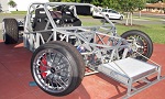
Warner R4 Build Diary

This project has now significantly changed (see below) from the early design, see the latest pages for the new project...
More information/vids available at: www.wr4.co.uk


[Edited on 27/2/09 by cloudy]
[Edited on 19/5/09 by cloudy]
[Edited on 8/6/09 by cloudy]
[Edited on 8/6/09 by cloudy]
www.warnercars.com
|
|
|
|
|
cloudy
|
| posted on 24/10/06 at 02:07 PM |
|
|
A few mock ups of front end shapes, it always almost looks better without it at all 
FUORISERIE, you mentioned you would do the front a bit differently any suggestions?
ideas + drawings welcome!


www.warnercars.com
|
|
|
FUORISERIE
|
| posted on 24/10/06 at 02:50 PM |
|
|
ok, send me a few 3/4 front and rear view and a side wiew image, for my rough sketches.
I tend to agree with you, it does look better with the steel tubes showing...
I will try .....but the concept looks really good, will see what i can do for you.
[Edited on 24/10/06 by FUORISERIE]
|
|
|
dr-fastlane
|
| posted on 24/10/06 at 04:21 PM |
|
|
That is a really cool buggy which you building. If I can do a suggestion for the front of the car. Perhaps its an idea to bend the top tube from the
nose round out of one tube, if you understand what I mean. It keeps the front of the car simple but smooth.
Greets Roy.
Rescued attachment buggy.JPG
------------------------------
I have not failed once. I have successfully found ways that will not work!
https://www.motor-forum.nl/threads/hardtail-dragstyle-project.343482/
|
|
|
thomas4age
|
| posted on 24/10/06 at 06:54 PM |
|
|
Looks very nice when it's this low to the ground, what ground clearance are you goin to run?
also not clear to me is what are you going to do with the diffcradle it looks like it's only attached to the rest of the chassis with 4
horizontal tubes? shouldn't that be braced very well?
grtz Thomas
btw nice project and should be quick aswell!
If Lucas made guns, Wars wouldn't start either.
|
|
|
cloudy
|
| posted on 24/10/06 at 07:05 PM |
|
|
diff mounts are not made yet, don't worry far more framework to surround it yet.
I like that design, i'll try it with photoshop
Ground clearance wise I will run about 120mm. I have 2x tiny 600kg electric rams, it would be quite cool to make a system to raise the front right up
for speed bumps - then I could run more like 100mm
Fuoriserie some plan views for you:


James
www.warnercars.com
|
|
|
cloudy
|
| posted on 24/10/06 at 07:15 PM |
|
|
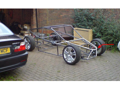
I'm really keen on that design dr fast lane - here's it in tubing

www.warnercars.com
|
|
|
Doug68
|
| posted on 25/10/06 at 12:31 AM |
|
|
Front tubes.
Have you built a stress model in the computer yet or a scale balsa model of the thing?
300kg is a very ambitious goal and I would guess youre trying to work out where the
tubes need to be to be effective rather than just what looks good.
If you keep at it long enough you should be able to make it work and look good at the same time.
Doug.
|
|
|
cloudy
|
| posted on 25/10/06 at 01:28 AM |
|
|
It's a good suggestion - i've tried a few bits of force analysis software to model it - but all go way over my head, and I just
dont' havce the time to learn how to use it properly. I've just been using common sense and judging myself how the forces are likely to
propagate
James
[Edited on 25/10/06 by cloudy]
www.warnercars.com
|
|
|
Doug68
|
| posted on 25/10/06 at 06:17 AM |
|
|
If the software is a mystery to you then build a 1/8th scale model of the frame using 1/8" square balsa and model glue.
Then pick it up and twist the thing.
Make another model of a cube X braced on all 6 sides say 100mm square and compare the 2 models.
Keep modifying your model until you are hard pushed to tell the difference between the 2 models.
Remember if your chassis is not stiff (which is different to strong). All the carfully worked out suspension geometry will go out of the window.
It may seem that this sort of stuff takes a lot of time when you could be welding things together, but I expect like me you want to make the best
vehicle that you can.
Doug.
|
|
|
iank
|
| posted on 25/10/06 at 07:43 AM |
|
|
Agree completely, a balsa model gives a really good idea of how stiff your chassis is, and is far more intuitive than a computer simulation. Takes an
evening, and you get to bore your mates with it  . If you need/want a number the FEA can be done later to confirm. . If you need/want a number the FEA can be done later to confirm.
It's amazing how one tube can make a huge difference, it's not something that can be done by eye, at least not until you've done a
few.
See this thread:
http://www.locostbuilders.co.uk/viewthread.php?tid=53918&page=1
Buggy looks really good so far BTW
[Edited on 25/10/06 by iank]
|
|
|
cloudy
|
| posted on 25/10/06 at 08:11 AM |
|
|
OK I shall give the model a go
|
|
|
FUORISERIE
|
| posted on 25/10/06 at 03:27 PM |
|
|
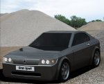
This was a personal project of mine, that due to time and work constraints I never came around in building it...., i
I couldn't build it myself, so why not have someoneelse try instead!.
Having seen your chassis, i thought about adapting my original design to your chassis setup.
this is just a very rough 10 min. sketch, but will be more detailed later in the process.
Let me know what you think, and if you like it?
]
[Edited on 26/10/06 by FUORISERIE]
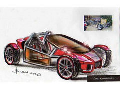 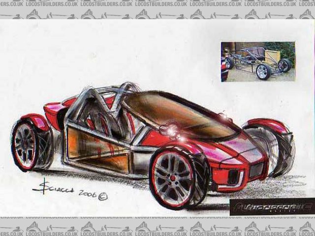
Rescued attachment img584.jpg
|
|
|
cloudy
|
| posted on 25/10/06 at 04:22 PM |
|
|
I love it, especially the nosecone area, You'd need to be pretty handy with fibreglassing!
PS: the "final" design for mine...

[Edited on 25/10/06 by cloudy]
|
|
|
ettore bugatti
|
| posted on 25/10/06 at 09:05 PM |
|
|
Looks cool,
I think with some extra tubes diagonal placed. You would end up with something much stronger.
What is the width of the interior and how much is the track f/r?
|
|
|
FUORISERIE
|
| posted on 26/10/06 at 09:49 AM |
|
|
quote:
Originally posted by cloudy
I love it, especially the nosecone area, You'd need to be pretty handy with fibreglassing!
PS: the "final" design for mine...
[Edited on 25/10/06 by cloudy]
Actually i think you wouldn't need much work for the nosecone,....... but I like your new bare bones chassis, maybe it looks better without the
body panels....
So no need for it, keep it simple as you have done.

|
|
|
cloudy
|
| posted on 26/10/06 at 10:55 AM |
|
|
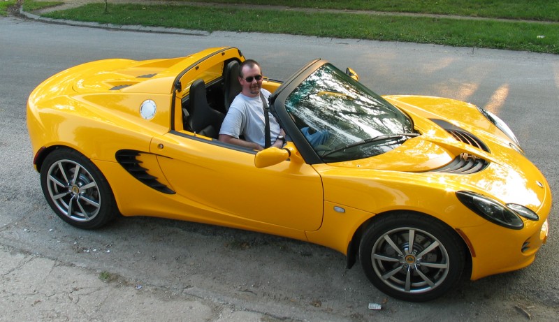
I was thinking of perhaps redoing the chassis when I got bored, and i'd like to loosely base the design on this:

Big problems are going to be making the panels, and getting glass to fit that...
James
|
|
|
iank
|
| posted on 26/10/06 at 11:19 AM |
|
|
Now that would be a big job.
If you are serious pick the glass first - wander round a big carpark to find something.
The front end looks a bit like the WLR, so getting a nose from them might be a good start for a buck.
[img][/img]
|
|
|
cloudy
|
| posted on 26/10/06 at 11:54 AM |
|
|
you might be onto something - the elise glass looks similar!
|
|
|
Dick Bear
|
| posted on 29/10/06 at 05:18 AM |
|
|
Creative juices...
There's nothing like seeing 10-minute sketches that look like auto design museum pieces, custom design frames that sit low and stable between
the wheels or a group of visionaries throwing out top-notched suggestions for the benefit of everyone to get the Creative Juices flowing!
Just two pages into Cloud's build and there's already been more helpful suggestions and imaginary response than some sites receive in a
year!
Great start, Cloud! may I suggest aluminum, hand-shaped body panels? Sure would be weight reducing,
Dick Bear
www.marketpointproductions.com
|
|
|
dr-fastlane
|
| posted on 30/10/06 at 07:33 PM |
|
|
The final design is great looking Cloudy!
I would not put on too much bodywork. The chassis has an raw and racing look, keep it that way. Perhaps it sounds funny but way not copy the looks of
a RC model (toy) buggy. Something like this, but with a glass front window, polycarbonate side windows (like most sevens) and some cycle wings.
Greets Roy
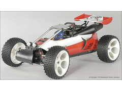 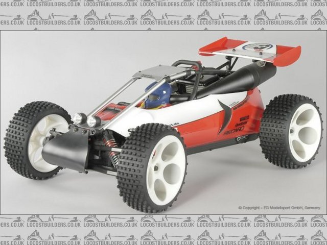
Rescued attachment Baja-Buggy.JPG
------------------------------
I have not failed once. I have successfully found ways that will not work!
https://www.motor-forum.nl/threads/hardtail-dragstyle-project.343482/
|
|
|
ZEN
|
| posted on 30/10/06 at 09:32 PM |
|
|
For me less is allways more and I like toys for big boys
My YouTube channel Cars, bikes - track days, motorsport, sim racing and more.
|
|
|
cloudy
|
| posted on 30/10/06 at 09:50 PM |
|
|
quote:
Great start, Cloud! may I suggest aluminum, hand-shaped body panels? Sure would be weight reducing,
Dick Bear
Sounds good, I think i'll follow everyone's suggestions and keep panelling to a bear minimum, except where requiured to keep away debris,
to help the shape or to improve aerodynamics..
When the chassis is finished (soon) I'll throw it up to the excellent talent here for some pointers
PS. dr fastlane - exactly the sort of car I was drawing inspiration from, definately a boy's toy!
James
[Edited on 30/10/06 by cloudy]
|
|
|
cloudy
|
| posted on 1/11/06 at 11:16 AM |
|
|
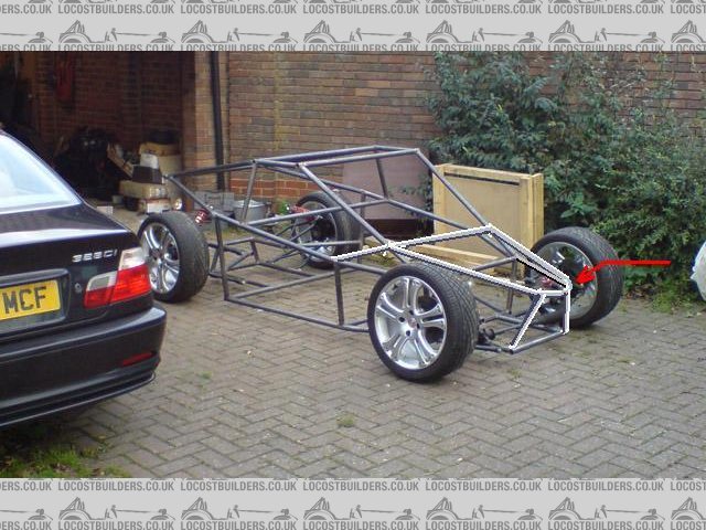
I've posted the below in the chassis section, but included it here as you midy guys probably are used to more weight over the rear
suspension.
OK I've welded the rear shocks on, it gives about 1" ground clearance with the bumps fully compressed and 2" as it starts to hit
the stops
This gives just over 10cm of suspension travel, with the car resting at about 6cm, leaving 4-5cm of upwards travel.

am I going to get away with this based on the photo + measurements above or do I need longer shocks?
James
[Edited on 31/10/06 by cloudy]
[Edited on 1/11/06 by cloudy]
|
|
|
Doug68
|
| posted on 1/11/06 at 12:02 PM |
|
|
This is a hard question to answer. But I'd think you'd want 2" at least of clearance at full bump. From reading the book a typical
locost has ~5" of static clearance and ~2" of travel from there to get to full bump.
More of a worry to me would be having the shock laid over that far. Effectively the suspension will get softer as its compressed, which if anything
is the reverse of what you want to happen. I'd get the shock as upright as possible.
Also I'd not want to put the load into the middle of the tube like that at the top end, hopefully you're planning bracing on it?
Similarly at the lower front wishbone point I'd want that braced, I guess I assume that theres going to be a lot more bracing everywhere?
But I'm possibly too worried about that sort of thing, after all I've been tinkering with my design for over a year now and still not got
a single weld done.
Doug.
|
|
|