cymtriks
|
| posted on 11/1/08 at 08:52 AM |

|
|
G loads on suspension
When suspension and chassis are stressed to a G load what is this value based on?
The unsprung mass multiplied by g?
The total mass on the corner multiplied by g?
The mass of the car multiplied by g?
Some other value?
Incidently I know of an actual test in which g was measured in a truck driving over potholes and speed bumps. The aim was to check what forces fragile
cargo would be subjected to. The answer was 3g.
|
|
|
|
|
JAG
|
| posted on 11/1/08 at 09:13 AM |
|
|
If you're analysing a whole vehicle then it would be the whole vehicle weight. However if your attempting to analyse a suspension
'corner' it would be whatever weight is being carried by that corner.
It's also direction dependant; can apply during cornering, straight line acceleration etc... 'g' is simply a unit of acceleration
based upon the acceleration due to gravity and allows you to multiply up the loadings on a component in any situation.
Justin
Who is this super hero? Sarge? ...No.
Rosemary, the telephone operator? ...No.
Penry, the mild-mannered janitor? ...Could be!
|
|
|
kikiturbo
|
| posted on 11/1/08 at 12:12 PM |
|
|
quote:
Originally posted by cymtriks
When suspension and chassis are stressed to a G load what is this value based on?
The unsprung mass multiplied by g?
The total mass on the corner multiplied by g?
The mass of the car multiplied by g?
Some other value?
Incidently I know of an actual test in which g was measured in a truck driving over potholes and speed bumps. The aim was to check what forces fragile
cargo would be subjected to. The answer was 3g.
the rule of thumb for road going vehicles is 5 4 3 G, i.e., 5 longditudionally, 4 verticaly, 3 side... that should take care of potholes.. multiplied
by corner weight..
also, when doing calculations, take worst case scenarios, i.e. not one force at a time but a combination of thos three..
|
|
|
nasty-bob
|
| posted on 11/1/08 at 03:05 PM |
|
|
Cymtriks,
I'm sure there will be a few differing opinions on this one.
I've always taken the worst case load on a corner ie max cornering and braking therefore most loaded wheel is the front outside. Calculate
weight transfer front/rear and then left/right.
Then you need to do a simultaneous equation to resolve wishbone forces by balancing linear forces left to right and taking moments about the contact
patch.
You will then need to apply a reserve factor of your own.
Damper mount loads. Well you have the reaction of the weight on this loaded corner vertically through the tyre, so you will need to resolve for the
load in the pushrod/damper. Shock/g loads are in addition to these. Whatever weight is on that corner, you are trying to accelerate (not just the
unsprung mass) as the damper should be considered solid. So you multiply the corner reaction force by the shock acceleration (whatever g you
choose).
I would say the shock values are rather more than 3g. The parcels acceleration would be damped as it has no mechanical link to the truck.
Do a quick calc on the vertical acceleration when hitting a 2inch bump at 60mph, that'll give you an idea- this is damped by the tyre though
Sorry if that was all a bit brief, but if you agree with this approach and have any questions, drop me an email and I'll try to help. I know you
are a very capable engineer and so I'm guessing I wont be telling you anything new though 
Cheers
[Edited on 11/1/08 by nasty-bob]
|
|
|
cymtriks
|
| posted on 13/1/08 at 10:27 AM |
|
|
quote:
Originally posted by nasty-bob
Shock/g loads are in addition to these. Whatever weight is on that corner, you are trying to accelerate (not just the unsprung mass) as the damper
should be considered solid. So you multiply the corner reaction force by the shock acceleration (whatever g you choose).
You know, I hadn't thought of that but you are completely correct, the dampers will be more solid over fast bumps/shock loads.
I would expect that loads due to cornering and braking are probably trivial.
How many bumps and pot holes are there for every corner or set of traffic lights?
Bumps are probably the major shock and fatigue issue.
quote:
Originally posted by nasty-bob
I would say the shock values are rather more than 3g. The parcels acceleration would be damped as it has no mechanical link to the truck.
Do a quick calc on the vertical acceleration when hitting a 2inch bump at 60mph, that'll give you an idea- this is damped by the tyre though
Ah yes.
60mph, 2 inch bump, 12 inches to max height (a small speed hump in effect)
Vertical shock of 80g!!!!!!! Eighty, not eight point nothing!
I suppose the tyres filter out most of this. The tyres are after all springs and dampers in their own right.
My figure of 3g is intriguing as it was measured in the back of the truck while being driven over a very bumpy car park.
I suppose if 3g is happening in the middle of the wheelbase then the suspension mounts over the bump, moving twice as far if you assume the other end
is not moving, must be experiencing 6g. i.e. S=1/2*a*t*t, so twice as far is twice the g. The load over one axle would be half the total so the load
is half the weight times twice the g, or, total weight times the measured g of 3g.
|
|
|
chriscook
|
| posted on 13/1/08 at 04:47 PM |
|
|
It's easy to get confused when people start talking about loads in terms of 'g' levels. A fairly standard 3g vertical bump
loadcase would be 3x the corner weight applied vertically - this does not mean that the wheel's acceleration is 3g for such a load
case. The 'g' term for loadcases is a convenient way to express that the load is normalised to the static load on that wheel.
3g is also a typical maximum whole body acceleration that you would measure on any vehicle with suspension be it a passenger car or a truck.
This is what was measured on the back of your truck an acceleration NOT a load.
Have a look at my post at the end of this thread
there is a link to a pdf of a presentation with some fairly industry standard loadcases
|
|
|
cymtriks
|
| posted on 13/1/08 at 05:33 PM |
|
|
Chris,
Is that corner weight the total weight on the corner or just the sprung weight?
I'd have thought that if a load is present then, by F=ma, there must be an acceleration and vice versa.
That's a very interesting table in the link but I can't see any reference to how the "g" factor is used, i.e. a factor applied
to corner weight or to some other value.
Where do you work btw?
|
|
|
chriscook
|
| posted on 13/1/08 at 06:01 PM |
|
|
quote:
Is that corner weight the total weight on the corner or just the sprung weight?
Given the approximate nature of the loadcase and the need to design in a safety factor to the design of your suspension I'd go for the total
corner weight. For most vehicles it won't make a huge difference.
quote:
I'd have thought that if a load is present then, by F=ma, there must be an acceleration and vice versa.
Yes I will not argue with Newton. But in real life with dynamic systems it is often difficult to know exactly what mass is being accelerated.
quote:
That's a very interesting table in the link but I can't see any reference to how the "g" factor is used, i.e. a factor
applied to corner weight or to some other value.
They will be relative to the corner weight I'd expect. I think some say you also need to take into account the weight transfer under
braking/cornering for some of the loadcases.
Remember that these loadcases are basic first off design loads which will probably cover the envelope in which your suspension will work different
companies will use different values. At such a level I wouldn't be worried about 10-20% here and there. Now if you start doing fatigue analysis
then its an entirely different matter and you need some decent data.
quote:
Where do you work btw?
MIRA - collecting and analysing road load data
What type of vehicle are you looking at this for?
|
|
|
Puk
|
| posted on 19/1/08 at 02:15 PM |
|
|
This may be of help...
I'm not saying this is how the professionals do it, but this is how I applied G loads to an FEA model for an analyses at university (back in
1992 - ideas may have moved on). I recall at the time that there was no definitive "thats the way to do it" moment - but the approach did
merit the award of a first for the final year dissertation. The car was a mid engined BEC of similar configuration to an Elise and in a pleasant
coincidence the chassis was of similar configuration being twin torque tubes either side of the passenger space joined by a number of transverse
bulkheads. My torque tubes were composite aluminium panels rather than the extrusions that Lotus employed.
2 load types were considered, those that resulted from accelerating the car (brake, cornering, acceleration and bump) and a torsion test.
The 1st set of load cases were modeled by:
* The loads were assumed to apply through the suspension pick up points
* A "global acceleration" was applied to the complete model. This introduce the loads created by accelerating the mass of the chassis
panels themselves.
* The loads imposed on the chassis by accelerating the major car components were modeled by applying the forces that would result at the
appropriat points on the chassis model. The major masses were:
o engine and gearbox unit
o driver and passenger
The panels were modeled using ANSYS' STIFF99 shell elements.
So considering brake loads the following constraints were applied:
Taking the road as being the XZ plane the front suspension pickup were fixed in the X, Y and Z planes
The rear pickup were fixed in the Z plane.
Reading back through the analyses a couple of simplifications jump out:
* Although the model did allow for weight transfer affects it did not model the loads on the chassis that result from the brake calipers trying to
twist themselves around their hubs.
* The loads were assumed to be quite a bit lower than those that are accepted now, being:
o 2.5G braking
o 2G lateral acceleration
o 2G acceleration
o 5G bump (this load case created the highest stress levels)
* the target torsional stiffness was 6.8 kn (I think that this value came from Vehicle Dynamics by Barstow but it may have been Costin &
Phipps))
As I say it was along time ago, and although I was able to get guidance as to how to use the FEA tool, I didn't find any standard methods of
modeling the loads on a car chassis.
I'm currently designing a Lotus 7 using similar chassis format and hoping that the FEA tools within SolidWorks will prove adequate. So any
construction criticism of this approach would be very welcome.
Cheers,
Puk
Before you judge a guy, walk a mile in his shoes. Then when you judge him, you're a mile a way and you've nicked his shoes.
|
|
|
cymtriks
|
| posted on 19/1/08 at 07:51 PM |
|
|
quote:
Originally posted by chriscook
What type of vehicle are you looking at this for?
Thanks for the link, very interesting! I'd like to make my own car one day, I have a couple of midengined designs in mind and wanted some guide
as to loading on the chassis.
I have made FEA models of several designs but these were aimed at establishing the stiffness, not the strength.
|
|
|
cymtriks
|
| posted on 19/1/08 at 08:07 PM |
|
|
quote:
Originally posted by Puk
Lots of interesting stuff
My FEA models are in Nastran. I do FEA for a living!
My models assume that the rear suspension mounts are fixed vertically and that loads, up and down, are applied at the front mounts to give a twisting
couple.
I'm happy that I can design a STIFF chassis for a given weight but most of the stuff I can find on "g" loads, so that I can assess
the STRENGTH is a bit obscure, hence the original post.
I wonder how people who stress chassis assume they are supported?
One way would be to fix three suspension mounts vertically (or other directions as required) and apply the "bumps" at the fourth.
However this has to be wrong, real chassis are not supported like that!
I suppose I could put spring elements in but then I'm adding complications and changes that might not be assumed in the g loads commonly
quoted.
It's a while since I read Costin and Phipps (from the library) and I can't recall how they assumed loads were reacted.
I doubt that the g loads assumed in traditional methods are actually based on a fully dynamic FEA model with all the spring stiffnees and masses in,
which is what is actually required.
|
|
|
Uphill Racer
|
| posted on 20/1/08 at 02:13 AM |
|
|
quote:
Originally posted by cymtriks
quote:
Originally posted by Puk
Lots of interesting stuff
My FEA models are in Nastran. I do FEA for a living!
My models assume that the rear suspension mounts are fixed vertically and that loads, up and down, are applied at the front mounts to give a twisting
couple.
I'm happy that I can design a STIFF chassis for a given weight but most of the stuff I can find on "g" loads, so that I can assess
the STRENGTH is a bit obscure, hence the original post.
I wonder how people who stress chassis assume they are supported?
One way would be to fix three suspension mounts vertically (or other directions as required) and apply the "bumps" at the fourth.
However this has to be wrong, real chassis are not supported like that!
I suppose I could put spring elements in but then I'm adding complications and changes that might not be assumed in the g loads commonly
quoted.
It's a while since I read Costin and Phipps (from the library) and I can't recall how they assumed loads were reacted.
I doubt that the g loads assumed in traditional methods are actually based on a fully dynamic FEA model with all the spring stiffnees and masses in,
which is what is actually required.
Go back to basics, learn your trade from first priciples then open the puter for fea.
Sorry thats the nicest way I could put it
|
|
|
Puk
|
| posted on 20/1/08 at 11:38 AM |
|
|
LOL - thanks for saving us from the first draft of your mail! But seriously Uphilll Racer if you can point me at a good reference then I'd be
grateful.
Cymtriks I think that it was Costin & Fipps (library copy too) that suggests the torsion stiffens target. From memory I don't think they did
cove the design of the structure to achieve this but rather described testing the completed chassis. Still the torsional stiffness target has the
advantage of being easy to comprehend an easy to model (be that on paper or 'puter). But there is always the nagging fear that hitting a kerb is
going to crumple your pride and joy :-(
Kikiturbo - where do the "5 longditudionally, 4 verticaly, 3 side." accelerations come from? I've seen them quoted in the internet
previously but without any explanation. Dennis "dpcars.net" Palatov suggests 4G in each direction but again I'm not sure where the
figures come from.
Whichever is chosen the approach suggested by Nasty Bob to derive the force applied to the outside front wheel looks straightforward.
That leaves the question of constraints unanswered.
Assuming that the road is the XZ plane, with X parallel to the longitudinal axis of the car and Z is up, does the following make sense?
Fix the rear wishbone mounts in X & Z, the damper mount fixed in Z.
The inside front wheel, it should be free to move upwards and longitudinally but would be pulled towards the inside of the curve. The force pulling it
in would be a function of the load on it, slip angle, friction coefficient. There must be a way of simplifying that! So no constraints just the
appropriate forces acting in Y and Z.
It would be interesting to see whether a chassis that hits the torsional stiffness target is strong enough to cope with the worst load case.
Before you judge a guy, walk a mile in his shoes. Then when you judge him, you're a mile a way and you've nicked his shoes.
|
|
|
Ians
|
| posted on 20/1/08 at 06:45 PM |
|
|
Finite element analysis is no substitute for good engineering. It is a tool for a good engineer, nothing more. It is up to the design engineer to
determine which problems would benefit most from its application and apply it to the understanding and resolution of those problems. A finite element
representation can certainly give you figures with great accuracy with likewise complexity but in the first instance how do you know if this
figure/figures is what you want or indeed need. One has to first make an assumption that the integration of all the constituent parts are going to
provide the anaylsis results representing true real world comparisons. IanS
|
|
|
Uphill Racer
|
| posted on 20/1/08 at 11:07 PM |
|
|
quote:
Originally posted by Ians
Finite element analysis is no substitute for good engineering. It is a tool for a good engineer, nothing more. It is up to the design engineer to
determine which problems would benefit most from its application and apply it to the understanding and resolution of those problems. A finite element
representation can certainly give you figures with great accuracy with likewise complexity but in the first instance how do you know if this
figure/figures is what you want or indeed need. One has to first make an assumption that the integration of all the constituent parts are going to
provide the anaylsis results representing true real world comparisons. IanS
You make it sound easy Ian, and it is isnt it if you have the knowledge to make the 'assumption'.
BUGGER......WHY AM I HERE.
No, not I think therefore I am.
|
|
|
kikiturbo
|
| posted on 21/1/08 at 06:08 AM |
|
|
Puk... the 5,4,3 rule comes from Greg Locock who designes suspension and other automotive systems for a livving.. he can be found on various forums,
namely Eng-tips (reccomended) and atlasf1... here is one of numerous desgn loads thread from atlasf1/autosport :
http://forums.autosport.com/showthread.php?s=&threadid=98827
or
http://www.eng-tips.com/viewthread.cfm?qid=203004&page=2
eng tips is worth a read.... great forum..
|
|
|
Puk
|
| posted on 21/1/08 at 08:37 AM |
|
|
Kikiturbo thanks for the site links. I just logged into eng-tips, it will take an extraordinarily act of will power to avoid frittering the day away
browsing the site!
Cheers,
Puk
Before you judge a guy, walk a mile in his shoes. Then when you judge him, you're a mile a way and you've nicked his shoes.
|
|
|
Ians
|
| posted on 21/1/08 at 07:29 PM |
|
|
Uphill racer
My intention was certainly not to make it sound easy, just the opposite. Lots of definitive "assumptions" have to be employed unless you
can be 100% sure that, say in the case of a spaceframe structure, every weld has 100% integrity and build in to your FEA equation the fact that on
composite monocoques even with high grade professional purchases delamination can be a factor. FEA when carried out on clearly defined and graded
aluminium billet machined parts can offer a greater area of accuracy within FEA analysis.
As an initial design aid it works well but at the end of the day empirical testing is just as important. (I am sure all F1 tubs etc have been fully
FEA processed but are still required to undergo crash testing.) When I was commissed to build Allan Staniforth's present hillclimb car, Allan
sent me his handmade scale balsawood chassis. A simple torsional twist fractured one of glued joints. Was this a fault in design or simply not enough
glue in that area???? So I have to reiterate, it is not as simple as plot it out on the computer and move a few nodes around. Ians
|
|
|
cymtriks
|
| posted on 21/1/08 at 11:13 PM |
|
|
quote:
Originally posted by Uphill RacerMy models assume that the rear suspension mounts are fixed vertically and that loads, up and down, are
applied at the front mounts to give a twisting couple.
I'm happy that I can design a STIFF chassis for a given weight but most of the stuff I can find on "g" loads, so that I can assess
the STRENGTH is a bit obscure, hence the original post.
I wonder how people who stress chassis assume they are supported?
One way would be to fix three suspension mounts vertically (or other directions as required) and apply the "bumps" at the fourth.
However this has to be wrong, real chassis are not supported like that!
I suppose I could put spring elements in but then I'm adding complications and changes that might not be assumed in the g loads commonly
quoted.
It's a while since I read Costin and Phipps (from the library) and I can't recall how they assumed loads were reacted.
I doubt that the g loads assumed in traditional methods are actually based on a fully dynamic FEA model with all the spring stiffnees and masses in,
which is what is actually required.
Go back to basics, learn your trade from first priciples then open the puter for fea.
Sorry thats the nicest way I could put it
So the correct way to support the chassis (or the way that ties in with the assumed loads) is?
First principles require that you understand how a structure is supported (or is assumed to be supported) in order to stress it.
For stiffness this is fairly simple as you can apply a couple at the suspension mounts at one end of a chassis while holding the mounts at the other
end vertically.
But for the various combinations of forces at the wheels needed to assess suspension loads it is not clear from anything I've found how these
loads are assumed to be reacted.
As it's so basic, I'm sure you'll be able to explain it clearly.
|
|
|
cymtriks
|
| posted on 21/1/08 at 11:38 PM |
|
|
quote:
Originally posted by Puk
That leaves the question of constraints unanswered.
Assuming that the road is the XZ plane, with X parallel to the longitudinal axis of the car and Z is up, does the following make sense?
Fix the rear wishbone mounts in X & Z, the damper mount fixed in Z.
The inside front wheel, it should be free to move upwards and longitudinally but would be pulled towards the inside of the curve. The force pulling it
in would be a function of the load on it, slip angle, friction coefficient. There must be a way of simplifying that! So no constraints just the
appropriate forces acting in Y and Z.
Thanks for this, what you are saying is that longitudinal and lateral loads are resolved at the wishbone mounts and that vertical loads are resolved
at the spring mounts.
I think you have an x, y or z in the wrong place somewhere, if the the XZ plane is the road then Y must be vertical!
Effectively, in a vertical bump, this method assumes that the bump is trying to work against spring mounts at the other corners that are bolted to the
road.
Hmmm...
|
|
|
Puk
|
| posted on 22/1/08 at 08:26 AM |
|
|
Hmm indeed!
I'll have a ponder on this and see if sketching some free body diagrams doesn't make thing clearer. At least to me!
Cheers,
Puk
Before you judge a guy, walk a mile in his shoes. Then when you judge him, you're a mile a way and you've nicked his shoes.
|
|
|
Ians
|
| posted on 22/1/08 at 07:01 PM |
|
|
The most accurate way is to restrain and load by the hubs with included suspension links. This is how a car is tested in real world situations. It is
illogical to do tests anywhere other than from the hub mountings using a fixed shock. the degree of freedom of FEA is the same as a physical test.
Ians
 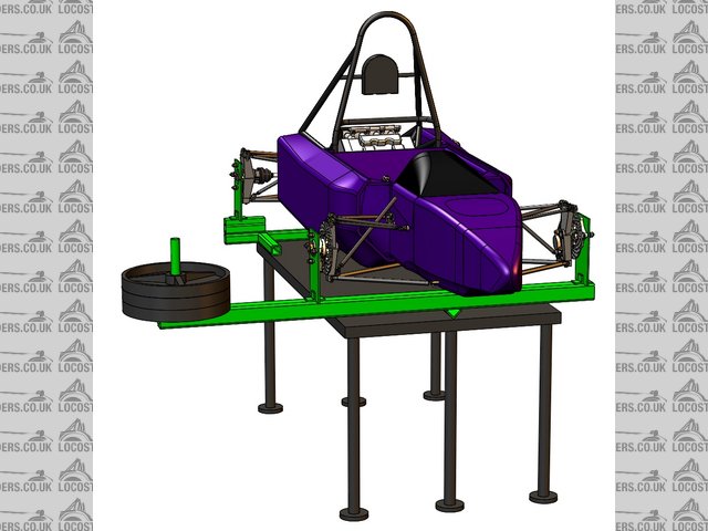
Rescued attachment torsion_screenshot_DT-5-10-04.jpg
|
|
|
Puk
|
| posted on 22/1/08 at 07:19 PM |
|
|
Hi IanS - I can see how that would allow to assess the combined torsional rigidity of the chassis and its wishbones. But does that help when trying to
establish whether introducing say a YG upward acceleration one one wheel combined with a XG longitudinal deceleration and a ZG lateral acceleration
(outer wheel hits pothole whilst bleading of brakes before apex of a bend) will cause plastic deformation?
Before you judge a guy, walk a mile in his shoes. Then when you judge him, you're a mile a way and you've nicked his shoes.
|
|
|
Ians
|
| posted on 22/1/08 at 08:17 PM |
|
|
Some theoretical data whilst we are always expanding our personal knowledge of a subject can often be superfluous unless backed up with physical
testing. Given that we find an answer to our problem, does this answer provide us with the solution. Determining accurate loading, is a complicated
process that yet again to use my favourite terminology requires some assumption making. In this case the projected (as yet undefined) loads should
indicate a worse case scenario. In the scenario you indicate, pot hole, braking, turning moment, would require some tyre data as compression and
aligning torque have to be included. The forces must also include vehicle weight and achievable weight transfers. Don't forget as measurable
loads it should also contain moments when the tyre is cantelevered off the wheel/upright. A tyre cannot experience 100% of longitudinal and lateral
loads at the same time. As these loads have a shock absorbing effect on the upright/wishbone/chassis mount etc where is this data obtainable from
(another assumption). Given that we cannot include one of the most important aspects of vehicle design/dyanmic loadings the next best solution is to
apply the loads at the spindle bearing centre. I feel that the best starting point is as you suggest, starting with a free body drawing. Whatever
ball parkyou end up in is going to be a large ball park. Sometimes a guesstimate on strengths required for certain components has to be just that.
Ians
|
|
|
Puk
|
| posted on 22/1/08 at 08:35 PM |
|
|
I'd forgotten how long it was since I had done any FBDs. I'm sitting surrounded by disintegrating text books!
Before you judge a guy, walk a mile in his shoes. Then when you judge him, you're a mile a way and you've nicked his shoes.
|
|
|