itsu-san
|
| posted on 22/5/11 at 10:59 AM |

|
|
ENGINE IN DAY!
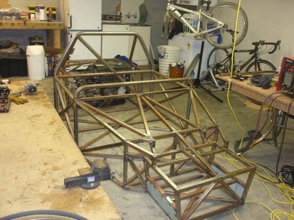
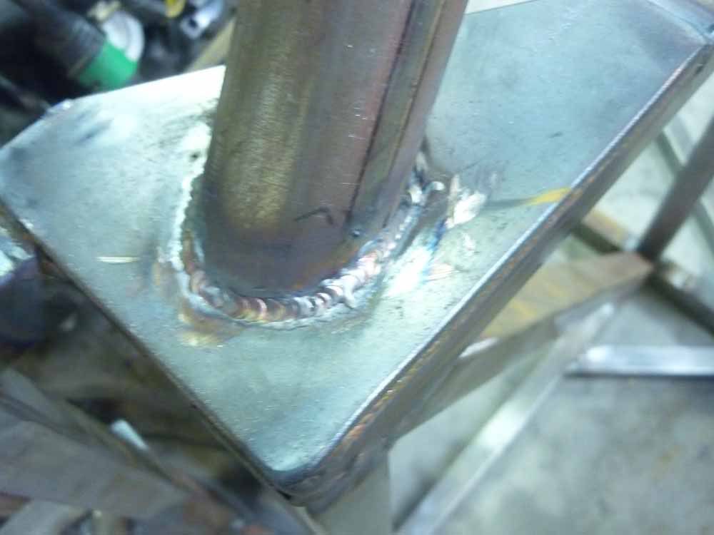
All the tig welding done by a mate. He's super talented with that torch! Slight problem with the engine fitment but other wise stoaked to bits!
|
|
|
|
|
itsu-san
|
| posted on 7/6/11 at 01:21 AM |
|
|
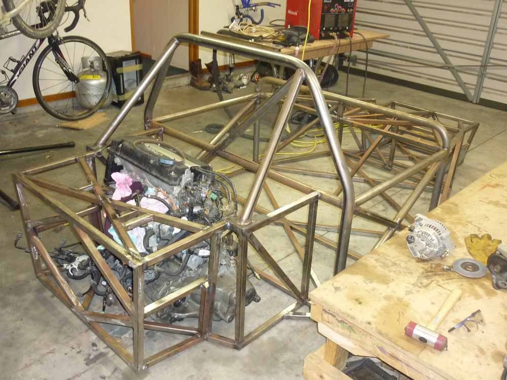
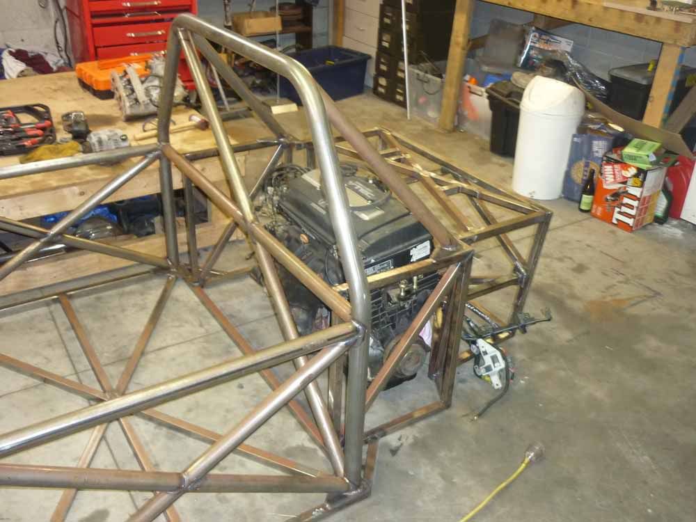
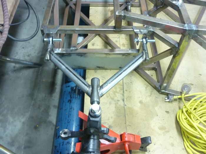
Quick update,
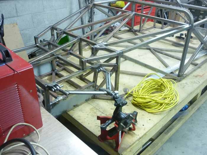
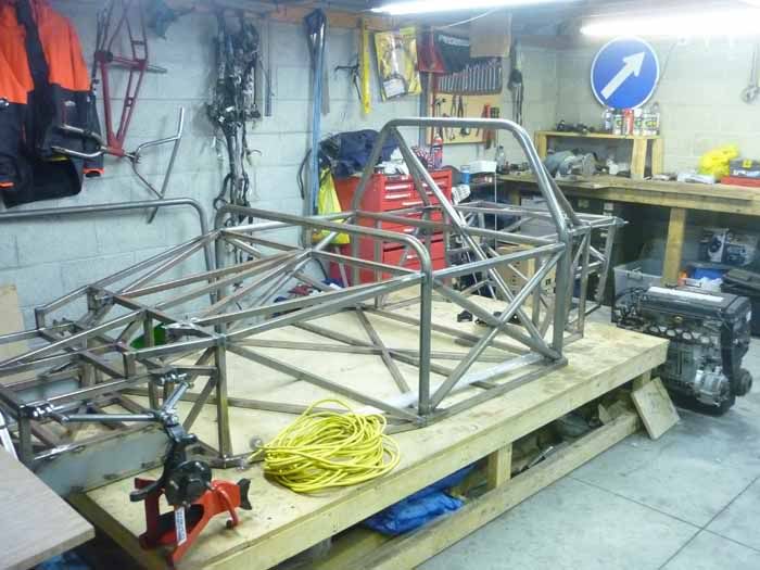
There's been alot of progress lately. The engine has been in the fame and the engine mount have been fabricated and painted. The engine sits in
the frame really nice.

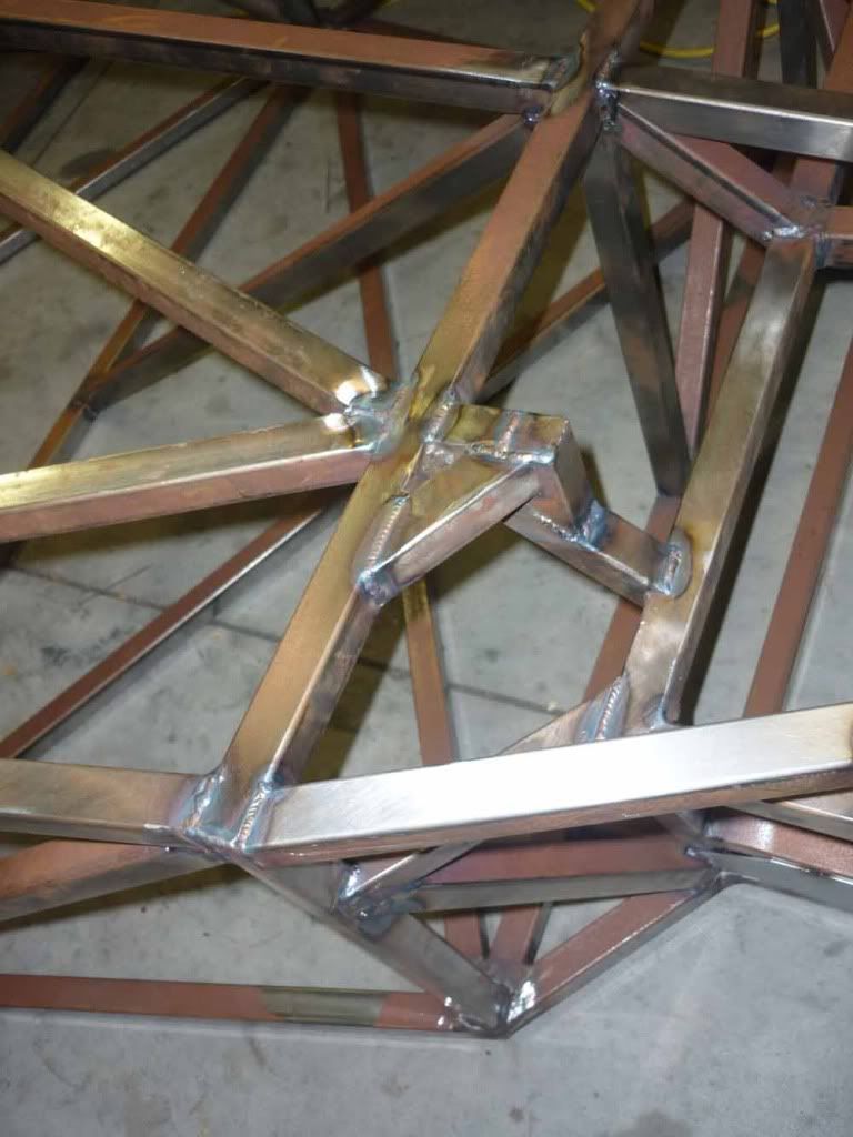
Started the wishbones.
Thanks
Grant
|
|
|
itsu-san
|
| posted on 4/7/11 at 01:02 PM |
|
|
Hope to be rolling in 7 days!
|
|
|
ceebmoj
|
| posted on 4/7/11 at 03:27 PM |
|
|
interesting update. What beings are you planning on using in the rockers?
|
|
|
coyoteboy
|
| posted on 5/7/11 at 12:37 AM |
|
|
Rod ends in bending?
|
|
|
itsu-san
|
| posted on 5/7/11 at 07:40 AM |
|
|
Thats all just sitting there at the moment. Waiting untill i get the rockers back from being coated to press in the bearings. The rod ends are not
loaded in bending. Thanks
|
|
|
coyoteboy
|
| posted on 5/7/11 at 10:20 PM |
|
|
Looks to me like they are in any sort of braking or acceleration?
|
|
|
itsu-san
|
| posted on 6/7/11 at 08:04 AM |
|
|
The very nature of a rod end means it can't react a bending load. I can see what you're saying though. The rod ends will be in shear but
thats fine. Thanks
|
|
|
v8kid
|
| posted on 6/7/11 at 09:01 AM |
|
|
To be pedantic rod end shanks are in bending and will fail (eventually - if they are loaded enough) where the locknut mates with the wishbone.
Can be a bit more than pedantic in the case of high loads for example in the bottom outer bearing but I see you have that sorted. Aurora have an
excellent article on bending loads in rod end shanks including worked examples. Looking at the sizes used I'd be very surprised if it was a
problem though
Cheers!
You'd be surprised how quickly the sales people at B&Q try and assist you after ignoring you for the past 15 minutes when you try and start a
chainsaw
|
|
|
coyoteboy
|
| posted on 6/7/11 at 09:25 AM |
|
|
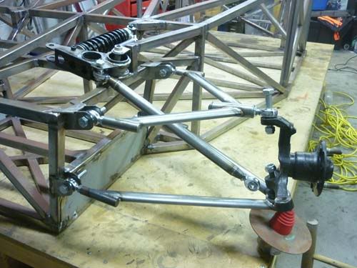
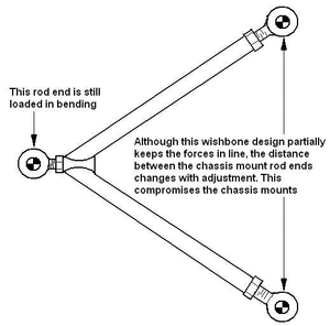
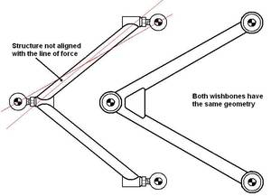
I think you're missing what I mean. In your upper A arm the two inner joints hold the arm rigid front to rear, the top rod end (when loaded by
braking torque) will be trying to move forward, resisted by the triangle. At which point your outer rod end is loaded in bending. Diagram time.

Your inner two are in shear primarily in he same situation (again, not ideal for a threaded part but possibly more acceptable), but there is a bending
component to that loading due to the misaligned load paths. I'll try to do a better diagram later.
Rod ends are designed to be loaded purely axially.
EDIT > I don't have to, an expert already did it for me:
http://www.formulastudent.de/academy/pats-corner/advice-details/article/pats-column-rod-ends-in-bending/
[Edited on 6/7/11 by coyoteboy]
|
|
|
itsu-san
|
| posted on 6/7/11 at 10:30 AM |
|
|
Ah yep im following you now. Thanks for the diagrams. You are right the outer rod end will be in bending. I think it will be ok but ill do some worst
case calculations tomorrow and post them up. Sometimes you have to compromise pure loading for other important atributes such as easy camber
adjustment and more economical construction. I better be able to justify myself on this point!
HA thats an excellent article and one i wish i had read before spending two weeks building these arms! Not exactly helpful when the only advice is to
'Build some non adjustable arms"
[Edited on 6/7/11 by itsu-san]
|
|
|
coyoteboy
|
| posted on 6/7/11 at 11:08 AM |
|
|
Oooh an I just threw together an FE example to show you the inners in bending too (forgive the rather crude box section steel lol):
Inners free to rotate but not translate, load applied at the outer rod end vertically:
http://www.dropbox.com/gallery/10257533/1/FEA?h=43392e
[Edited on 6/7/11 by coyoteboy]
|
|
|
v8kid
|
| posted on 6/7/11 at 11:47 AM |
|
|
For those who prefer to use the old ways 
BTW watch out it's big!!!


Cheers!
You'd be surprised how quickly the sales people at B&Q try and assist you after ignoring you for the past 15 minutes when you try and start a
chainsaw
|
|
|
itsu-san
|
| posted on 6/7/11 at 11:53 AM |
|
|
Hey thanks for that. FEA can be a good visualisation tool. Do you mind explaining you BC's and solver method? What was your load/magnification
factor? Cool seeing the compression buckling! Do you not think the inboard bending is in the arm rather than the rod end though? Have you seen any
top a-arm designs that utilizes pure tension and compression loading while still having independent camber adjustment?
Cheers
Grant
[Edited on 6/7/11 by itsu-san]
|
|
|
itsu-san
|
| posted on 6/7/11 at 12:06 PM |
|
|
Thanks v8kid! Interesting article. I have some thinking to do. 
|
|
|
kb58
|
| posted on 6/7/11 at 01:31 PM |
|
|
That's why it's so important to use check-nuts and that the seating surface is square to the shank. Tightened down, it moves the points of
highest stress away from the threads and onto the check-nut mating surface. And of course, also keeps the part from backing out!
[Edited on 7/6/11 by kb58]
Mid-engine Locost - http://www.midlana.com
And the book - http://www.lulu.com/shop/kurt-bilinski/midlana/paperback/product-21330662.html
Kimini - a tube-frame, carbon shell, Honda Prelude VTEC mid-engine Mini: http://www.kimini.com
And its book -
http://www.lulu.com/shop/kurt-bilinski/kimini-how-to-design-and-build-a-mid-engine-sports-car-from-scratch/paperback/product-4858803.html
|
|
|
coyoteboy
|
| posted on 6/7/11 at 01:32 PM |
|
|
quote:
Originally posted by itsu-san
Hey thanks for that. FEA can be a good visualisation tool. Do you mind explaining you BC's and solver method? What was your load/magnification
factor? Cool seeing the compression buckling! Do you not think the inboard bending is in the arm rather than the rod end though? Have you seen any
top a-arm designs that utilizes pure tension and compression loading while still having independent camber adjustment?
Cheers
Grant
[Edited on 6/7/11 by itsu-san]
Ignore the values, they were only put in to help aid visualisation of the problem as you say, and show bending in the rod end shank holding sections.
It was done in Solidworks using the static solver (FFEPlus) It used an unrealistic 5000N force at the outboard end with the force in the forward
direction as if under hard braking (not following the arm deflection, though that may be more accurate thinking about it, but the difference is
minimal). The inner joints were allowed to rotate freely in horizontal plane but constrained in location. Another in there now with narrowings for the
shanks of the rods, just highlights the bending in those spots.
The main bending moment is carried by your welded joint and the arm outboard of it, but there is still a bending moment in the rod shaft/arm joint
location (though fairly small). I don't have time to go through a full model (if you have the dims I can do it in about 2 weeks time but
I've a few things on my plate at the mo)
I've not seen any adjustable arms using pure tension/compression no, but I've no been looking tbh, I just spotted yours and thought you
should be aware of the possible issue in case it causes a safety issue. Most of the time we use adjustments at the upright instead, or just re-make
the arms with new geometry. It'll probably be fine for testing as you've covered the main lower arm outer joint problem, but I'd not
be using it on the road, personally.
|
|
|
v8kid
|
| posted on 6/7/11 at 01:49 PM |
|
|
quote:
Originally posted by kb58
That's why it's so important to use check-nuts and that the seating surface is square to the shank. Tightened down, it moves the points of
highest stress away from the threads and onto the check-nut mating surface. And of course, also keeps the part from backing out!
[Edited on 7/6/11 by kb58]
Interesting I never considered that. To maintain the stress distribution wouldn't the lock nut have to be tightened up to the UTS? If not as
deflection commences one side of the lock nut will loose contact with the shoulder on the wishbone I would think.
Tightening the lock nut up that tight would really worsen the bending stress though - possibly -I need to do a force diagram of it but can't be
bothered just now. I'll try googling it
Cheers!
PS I may be wrong here it depends on how the lock nut deforms it could be a bit of both scenarios leading to an overall gain - just as KB says. Phew -
it takes a while for my brain to get into gear but at least I can put it down to incipient alzheimer's at my age.
You'd be surprised how quickly the sales people at B&Q try and assist you after ignoring you for the past 15 minutes when you try and start a
chainsaw
|
|
|
coyoteboy
|
| posted on 6/7/11 at 02:18 PM |
|
|
Anim of the bending...
http://www.flickr.com/photos/bucklevision/5908375291/in/photostream
Regardless of check nuts, you still have the shank in bending (unless you're making no use of the check nut and have it right out at the bearing
end, minimising shank extension.
|
|
|
Doug68
|
| posted on 6/7/11 at 11:59 PM |
|
|
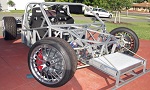
This is not that an uncommon thing to do, the picture below is from the RCR cars website and their vehicles
seem pretty well respected.

I think that the only answer is to know the specs on the parts involved and do the math to see if you're going to get anywhere near causing a
part failure.
Doug. 1TG
Sports Car Builders WA
|
|
|
itsu-san
|
| posted on 7/7/11 at 04:57 AM |
|
|
Interesting doug.
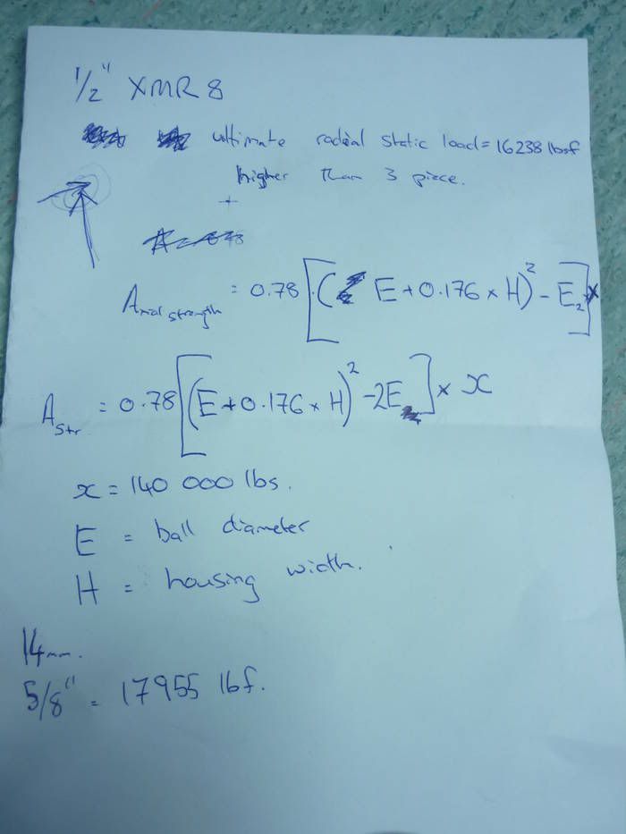
I managed to get some specifications for the rod ends today. The rod ends i have are for motorsport use and are of two piece design with a special
ball retantion chamfer which apparently makes them able to take a significant axial load! They are made from cro-moly and the shank strength is
similar to grade 8.8 bolts.
Just trying to find time to run the numbers now.
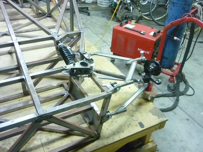
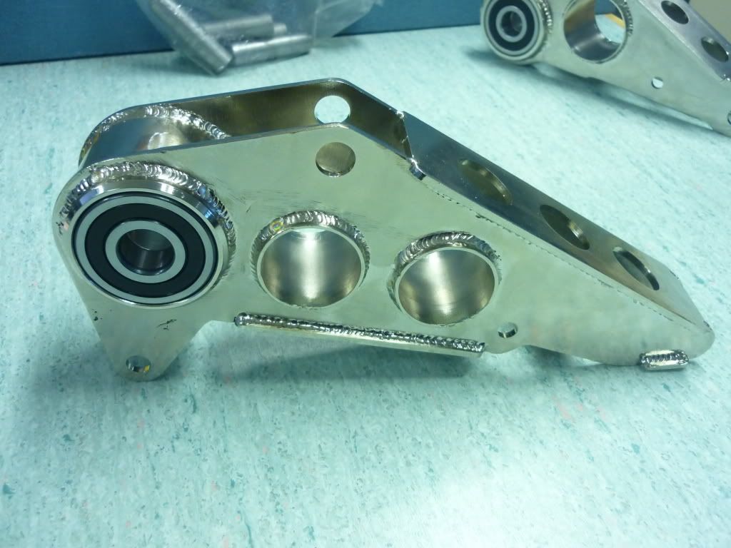
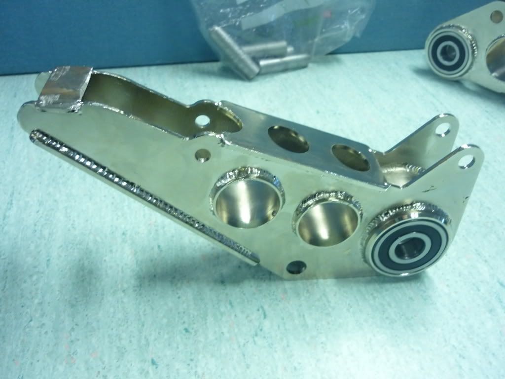
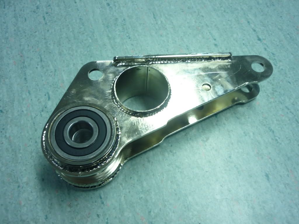
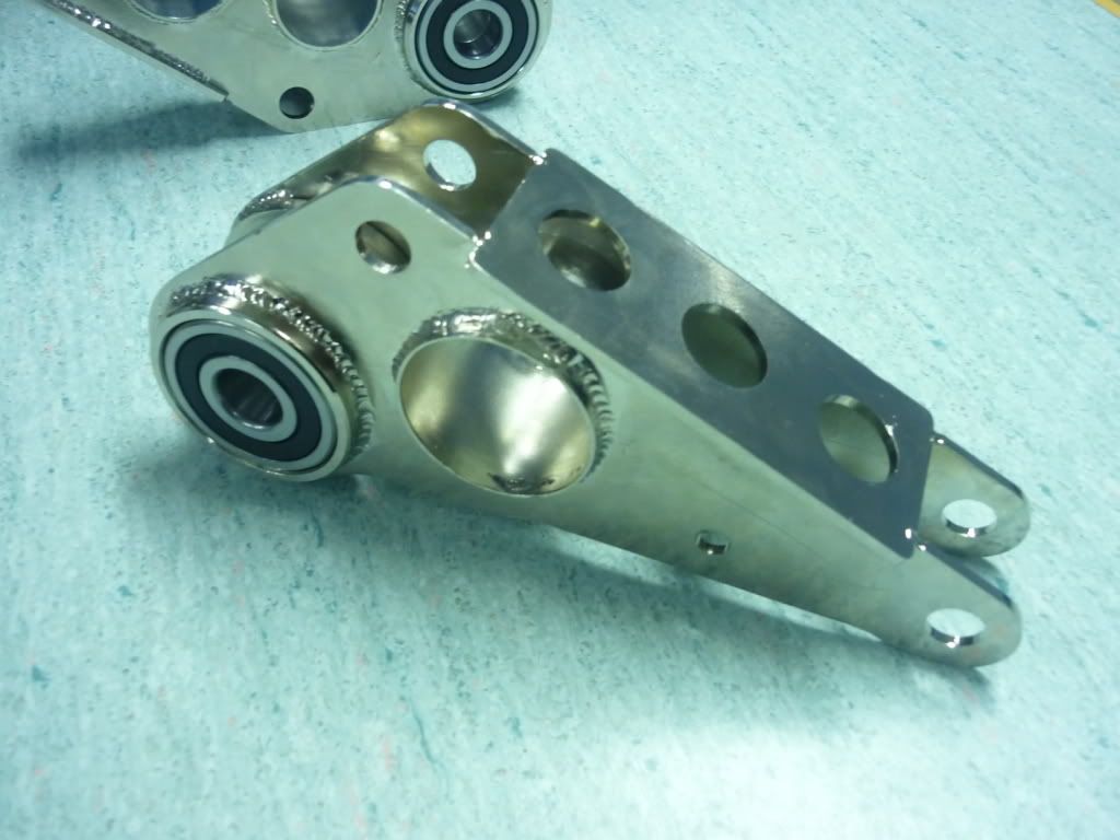
Got the rockers back from the platers and pressed the bearings in.
Thanks
G
[Edited on 7/7/11 by itsu-san]
[Edited on 7/7/11 by itsu-san]
[Edited on 7/7/11 by itsu-san]
|
|
|
coyoteboy
|
| posted on 7/7/11 at 01:42 PM |
|
|
Doug - those bones are tiny, making the leverage a lot lower, but I still don't think it excuses it - it's poor (sorry!) design for the
sake of easy manufacture. It's the number one, first and primary no-no in most modern suspension design instruction. If you can justify it by
calculating max loadings, proving cyclic stress on a threaded, notched part is within limits then fine, but it's so much better to do it the
right way.
Those rockers look beautiful!
[Edited on 7/7/11 by coyoteboy]
|
|
|
itsu-san
|
| posted on 7/7/11 at 02:08 PM |
|
|
Yes you are right and im very glad and thankful you have taken the time to explain this rod end in bending business. This is the problem with trying
to build a race car with no formal motorsport experience! I have done some preliminary calculations today and believe i can get away with this design
safely if i increase the outer top ball joint from a 14mm to a 5/8" rod end. It's not a nice design and if it was feasible to change it
without starting the whole car again i would but i need to continue with this design (as long as i can prove its not going to fail) and use it's
inherent adjustment to learn what geometry works for future projects.
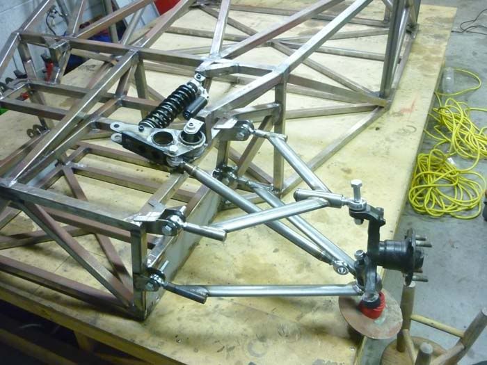
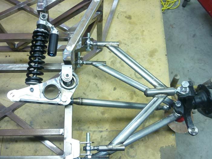
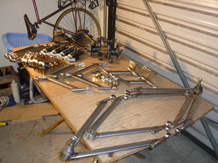
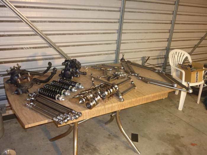
Here's all the components laid out ready to go. I need to spend about a day making a few more spacers then we should be able to get it rolling
in a day!
Ill get a peer to critique my load calculations and then i will post them up.
Thanks
Grant
[Edited on 7/7/11 by itsu-san]
|
|
|
coyoteboy
|
| posted on 7/7/11 at 02:47 PM |
|
|
TBH I'm pretty damn impressed with the lot, while the arm issue could be a problem (we'll see with your maths) it isn't terminal -
you could re-create the bones later with smaller offsets and a more suitable bearing/bushing style if it did pose a problem.
Keep up the good work.
|
|
|
v8kid
|
| posted on 7/7/11 at 04:10 PM |
|
|
Guys I really don't think there is a problem - race cars use 3/8" rod ends in the bottom lower outer wishbone and get away with it for a
while - but they do fail in that location.
Remember that by the time you get to the inner rod ends most of the forces have been divided by 2 or siphoned away by the springs.
Cheers!
You'd be surprised how quickly the sales people at B&Q try and assist you after ignoring you for the past 15 minutes when you try and start a
chainsaw
|
|
|