coyoteboy
|
| posted on 8/7/11 at 09:29 AM |

|
|
quote:
Guys I really don't think there is a problem - race cars use 3/8" rod ends in the bottom lower outer wishbone and get away with it for a
while - but they do fail in that location.
What race cars?
F1 cars often use mono-shock suspension, doesn't make it right for road use. And check out any decent rece vehicle and you will not find rod
ends on the lower outer joint at all. Hell, our student race team have a budget of 5K a year and don't use rod ends there on a car that weighs
in sub 200kg!
[Edited on 8/7/11 by coyoteboy]
[Edited on 8/7/11 by coyoteboy]
|
|
|
|
|
v8kid
|
| posted on 8/7/11 at 11:33 AM |
|
|
Err! Not sure how I've offended you but I thought that my previous post acknowledged that the bottom outer ball joint had already been
recognised as a high load item - that's why he has used a spherical joint to avoid the rod end shank bending entirely!
The race cars I see around me in the paddock have 3/8" spherical joints in other positions just go and look if you think I'm talking rot
 Perhaps I read the post wrong but I thought that this was principally a track car and hence does not need to be over-engineered. Perhaps I read the post wrong but I thought that this was principally a track car and hence does not need to be over-engineered.
Cheers!
You'd be surprised how quickly the sales people at B&Q try and assist you after ignoring you for the past 15 minutes when you try and start a
chainsaw
|
|
|
coyoteboy
|
| posted on 9/7/11 at 12:24 AM |
|
|
You've not offended me, not sure why you think you have?
You said "race cars use 3/8" rod ends in the bottom lower outer wishbone and get away with it for a while"
I just wondered which ones (ie what series etc), I'd be surprised if any serious race team used rod ends in the bottom outer wishbone location,
hence the question. All the ones I've been around have either non-RE arrangements in all locations or load their rod ends solely in the axial
direction.
Don't think it's a matter of over-engineering, it's a matter of engineering.
[Edited on 9/7/11 by coyoteboy]
|
|
|
itsu-san
|
| posted on 20/7/11 at 04:24 AM |
|
|
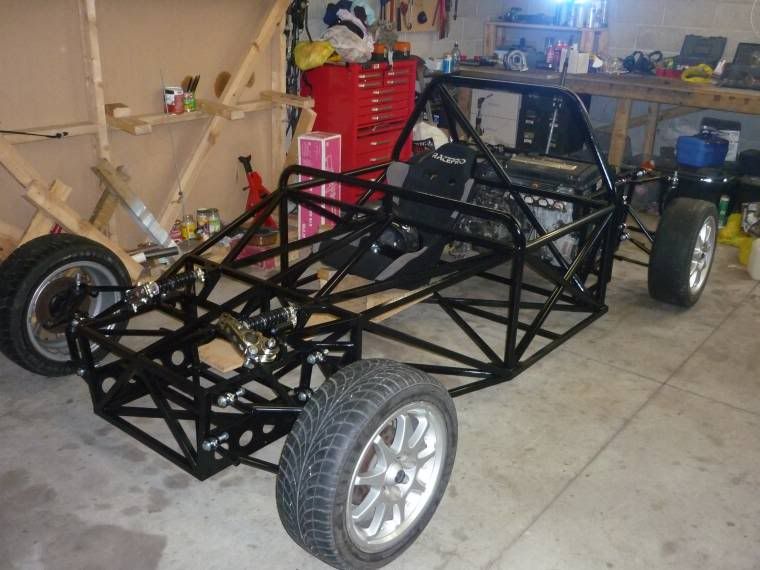
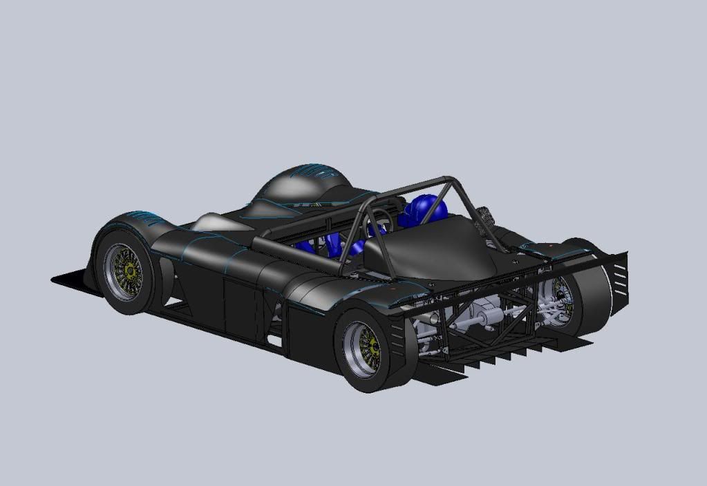
After two hard days finally got her off the table and sitting pretty!
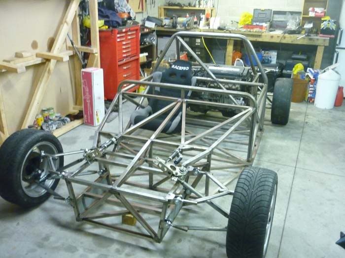
[Edited on 20/7/11 by itsu-san]
|
|
|
iti_uk
|
| posted on 4/8/11 at 08:37 PM |
|
|
Out of interest, did you do any FE analysis on the spaceframe? I'm concerned about the connection you have made between the front/rear boxes and
the central chassis. The bending stiffness of a chassis is dictated by transverse sections, of which the front/rear box connections
uneven/unprogressive geometry, and the torsional stiffness is dictated largely by joints, again the front/rear box joints look weak. Also, I'd
be concerned about anchoring your shocks on an un-triangulated cross-member. I'd expect to see deformation and therefore fatigue occurring
around that area. I'd second the comments made already about the wishbones. For an idea on how to have camber/castor adjustment on properly made
wishbones, have a look at how Mazda did it with the MX5 - bolts through slotted mounts located by eccentric washers. Very tidy.
All that said, good to see you're getting on well with the build. Should be one hell of a toy when it's finished.
Chris
|
|
|
itsu-san
|
| posted on 6/8/11 at 03:59 AM |
|
|
Hi Chris,
Thanks for voicing your concerns but i can't say i share them.
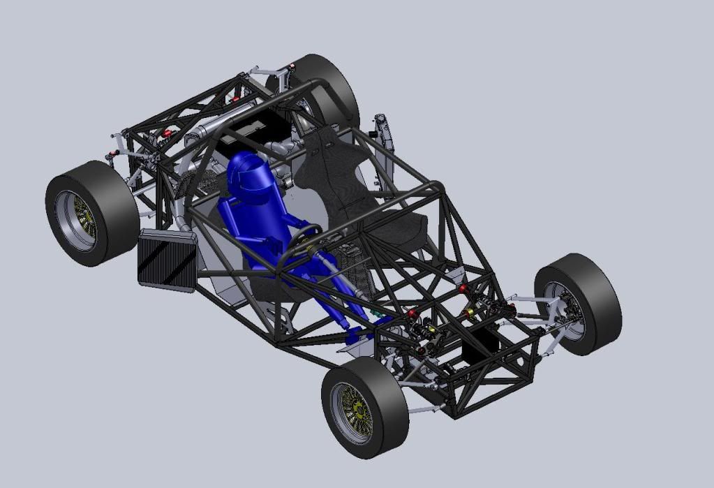
I did not conduct a FEA study on the chassis as for my build i don't believe it was warrented. This chassis is compromised by cost and
construction techniques. The chassis has it's members aligned on flat planes and single angle cuts that have allowed me to construct it in my
garage without a complex jig or notching equipment. It is far from simple to "do FEA on a frame" and get useful answers. The chassis has
been designed to be safe and to be built in my garage with torsional stiffness a secondary concern and im willing to accept whatever weight i end up
with for this car.
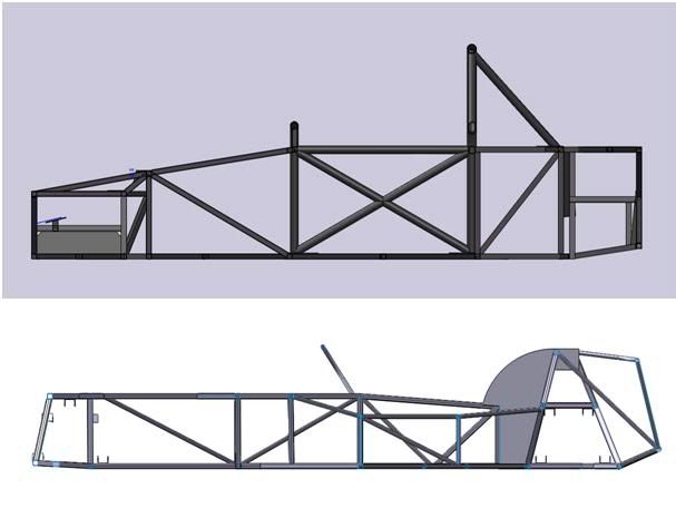
I have taken longitudinal profile of my chassis and compared it to that of your average 7 chassis. Just from visual inspection you can see my chassis
has a much higher second moment area and thus bending stiffness. Also keep in mind the chassis will be panneled with light gauge aluminium, further
resisting trapezing of those open profiles.
Chassis bending comparison
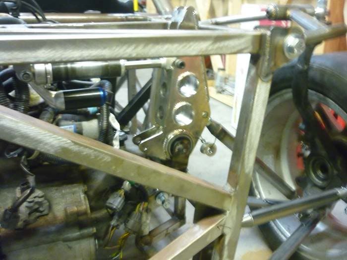
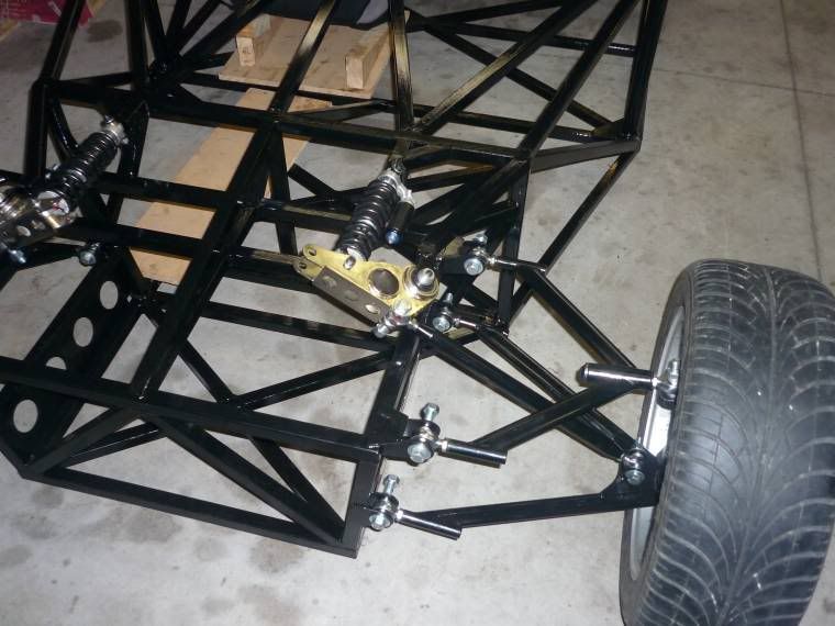
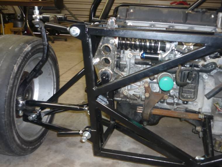
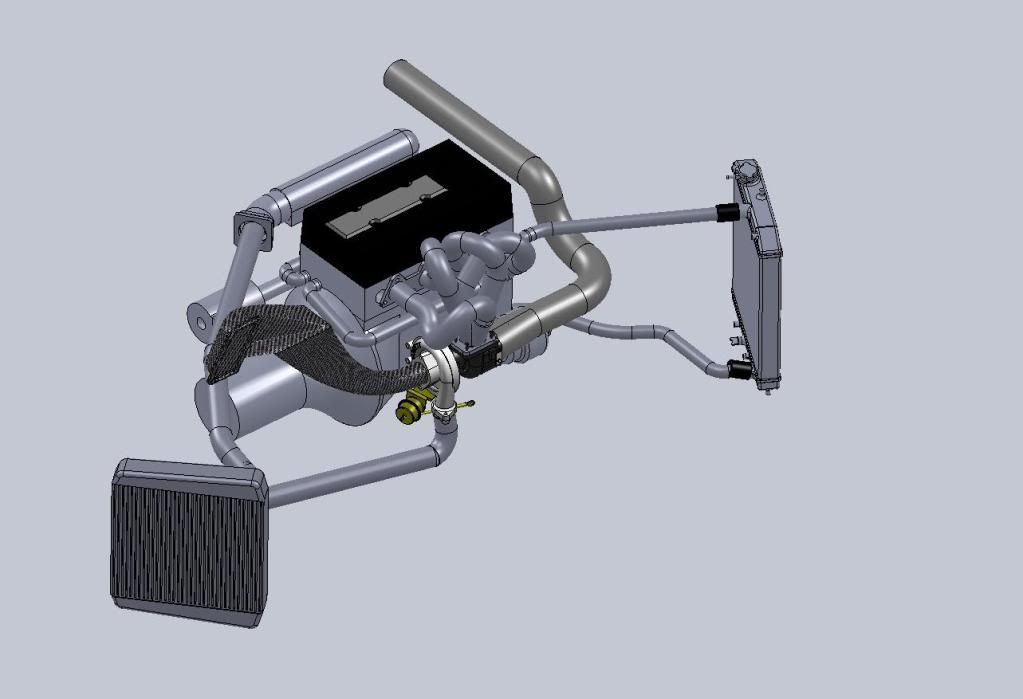
As for the shock mounts, im not sure what chassis you're looking at but the front shocks mount at point A in the picture below you can see the
load path here is well distributed. As for the rear shock mounts at B, again i cannot see you're problem with the load path. The mounts are well
triangulated and the loads are in tension and compression (generally).
Front and rear sections
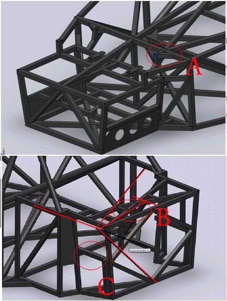
In case you were refering to the rocker mounting at C, thats a square cross section in bending and torsion. You can calculate the stress and
it's under the endurance limit for the chassis material (mild steel)
I personally don't like using eccentric sleeves for any kind of adjustment as i dont beleve these type of adjusters isolate the variables you
are trying to change well enough. Ie, you might be changing the static camber but you are also changing the roll centre height.
I've done the calculations for the rod ends in my suspension and im happy its going to be safe even though its not an optimal design. 
Thanks
Grant
|
|
|
itsu-san
|
| posted on 17/8/11 at 11:36 PM |
|
|
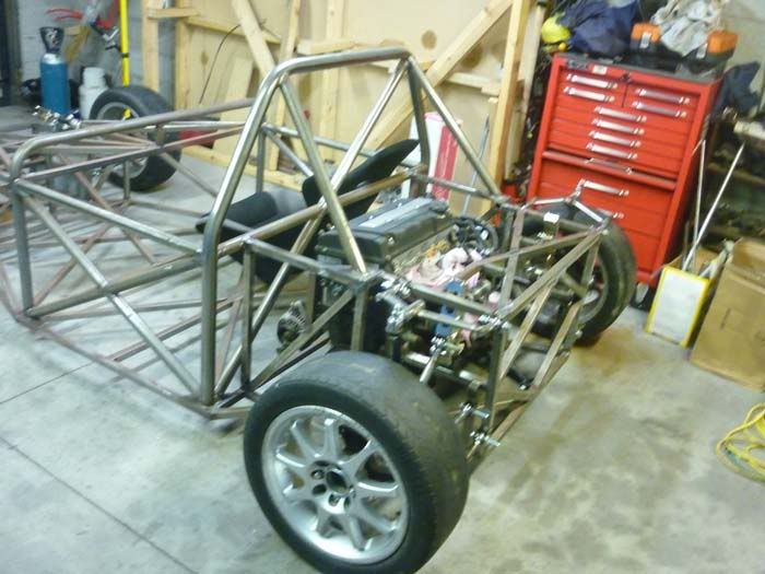
Got the chassis in etch primer and the suspension arms back from being powder coated.
Next up is extending the steering rack!
|
|
|
Doug68
|
| posted on 20/8/11 at 09:07 AM |
|
|
Hi Itsu san,
Looking at you frame again, at the rear of the car where I think iti_uk is refering to is below...
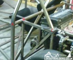
I think when loaded the member B-C will either be in tension or compression depending upon whats going on, this'll put member A thru B and on to
the other side in a bending condition. Which we all know is not good.
Another member from A to C would fix this, or if there's going to be a roll bar brace going forward this could probably achieve the same result.
Doug. 1TG
Sports Car Builders WA
|
|
|
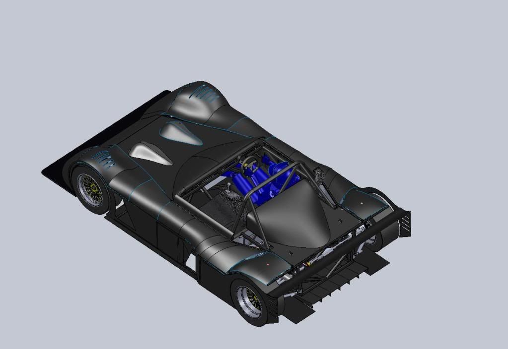
itsu-san
|
| posted on 29/1/12 at 12:09 AM |
|
|
|
|
|
itsu-san
|
| posted on 29/1/12 at 01:30 AM |
|
|
|
|
|
Ivan
|
| posted on 29/1/12 at 09:10 AM |
|
|
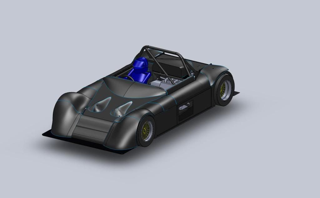
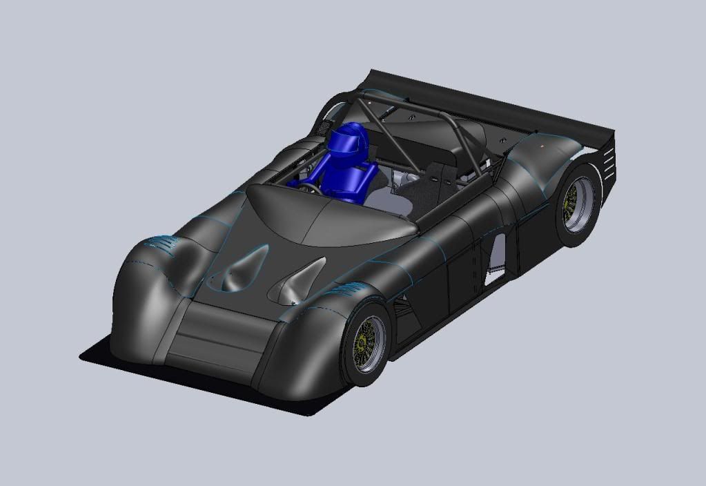
I know it looks better but why have you gone to the much more difficult to build compound curves on the wings from your initial design which I thought
was cool.
|
|
|
redbeard
|
| posted on 29/1/12 at 09:48 AM |
|
|
Rear Uprights
Hi Great build
Curious what are the rear uprights from ?
Also like to oval rubes for wishbones - Wahat are sizes/ thickness
|
|
|