Bob C
|
| posted on 6/1/06 at 11:34 PM |

|
|
EXUP - getting rid of error codes
I put a small circuit together to get rid of the EXUP error code on an R1. And it works!!! (cue post from Jimgiblett saying it doesn't work any
more. . . . )
Anyway it's just 3 resistors, a transistor a capacitor and a zener - very easy to make,(much simpler than alternative circuits I've seen
on the web)
Any small signal npn transistor will do - BC847 if you have to go to maplins for one... the zener's 5.1V and the capacitor is 1uF
cheers
Bob
http://www.locostbuilders.co.uk/photos.php?action=showphoto&photo=exup.jpg
|
|
|
|
|
Paul G
|
| posted on 7/1/06 at 01:18 PM |
|
|
I'm not using the R1 clocks so are there any other reasons not to remove the exup valve? I still have it plugged in hanging in the engine bay,
I'd take it out but am not sure if doing so will affect anything else - does the ecu know if its there or not?
Cheers
Paul
|
|
|
zxrlocost
|
| posted on 7/1/06 at 01:25 PM |
|
|
I was under the impression that if its plugged in its happy
|
PLEASE NOTE: This user is a trader who has not signed up for the LocostBuilders registration scheme. If this post is advertising a commercial product or service, please report it by clicking here.
|
locoboy
|
| posted on 7/1/06 at 01:43 PM |
|
|
whats the price of making one of these jobbies?
Im planning on just mounting my exup valve under the dash.
ATB
Locoboy
|
|
|
progers
|
| posted on 7/1/06 at 02:37 PM |
|
|
Paul G,
There is no reason why you cannot remove the EXUP valve, it has no effect on the running of the ECU etc.
The error code on the R1 clocks is the only downside (and that can be eradicated when the engine is running by shorting the EXUP wires together). BoB
C's circuit additionally stops the error code when the ignition is on but the engine is not running. Nice to see someone come up with an
economical solution to that.
Cheers
Paul
|
|
|
Paul G
|
| posted on 7/1/06 at 03:30 PM |
|
|
Nice one fellas, thats another kilo saved!
|
|
|
Bob C
|
| posted on 7/1/06 at 05:52 PM |
|
|
Cost? these are all 2p components + a couple of cm of veroboard. If you know anybody who's into electronics they'd knock it up in no
time.
A soldering iron is probably not a bad investment for a car builder anyway for splicing looms & such, all the bits are at maplins & similar
stores.
cheers
Bob
|
|
|
smart51
|
| posted on 7/1/06 at 07:22 PM |
|
|
The EXUP servo connects only to the ECU. The ECU must send an error message to the clocks. I doubt that the ECU would stop the bike running jsut
because the EXUP is broken but I guess there may be a possibility of it limiting something - a kind of limp home mode. I've never heard of such
a thing though.
The circuit shown below can be yours for less than £1, plus a small box if you want to do it right. Sounds like a bargain to me. As an electronics
engineer, I might have tried that before riveting my EXUP servo to my engine cradle.
|
|
|
progers
|
| posted on 7/1/06 at 07:38 PM |
|
|
Just to clarify that there absolutely is NOT any kind of limp home mode or reduced performance map from the R1 ECU if the EXUP is not there.
Race teams junk the EXUP and they would not do this if it had any adverse effect on engine performance. Also all the best aftermarket exhaust systems
for the R1 junk the EXUP too. You can happily resign it to the scrap bin :-)
Cheers
Paul
|
|
|
jimgiblett
|
| posted on 7/1/06 at 08:07 PM |
|
|
Just to say its all working fine.
The method of display of the diagnoistic codes on the 98-01 clocks is different to that on my 03 inj R1. Where as you get the Tacho tango on the
carbed engine you get proper numeric diagnostic codes on the inj model. More significantly though, where as with the carbed model clocks the error
code was only present when the ignition was on but the engine not running. The inj 03 clocks continue to give a diagnostic error while the engine is
running which is more than a little annoying. So a big thanks from Bob for fixing this with his circuit.
ps. As Paul says no limp home mode and if you are not running the bike clocks probably of no consequence.
[Edited on 7/1/06 by jimgiblett]
|
|
|
R1minimagic
|
| posted on 8/1/06 at 01:08 PM |
|
|
I cannot get rid of the exup error on my 98 R1. I tried plugging the motor in, a vtac circuit, shorting etc as recommended on the web but non of them
make it go away. I have had to connect my tacho directly to the ignition coils.
Also, can't get my acumen gear indicator working above 2000rpm, as soon as i rev it loses the signal!
Any ideas please??!!
|
|
|
smart51
|
| posted on 8/1/06 at 07:46 PM |
|
|
R1minimagic, are you connecting both plugs to your EXUP motor? I believe that one of them connects via a bullet connector. IF that is OK, bell out
the wires from the ECU plug to the EXUP plug. Check that your loom is OK. After that, try borrowing an EXUP servo off someone to see if that is the
problem, otherwise it might be your ECU.
|
|
|
OX
|
| posted on 8/1/06 at 08:58 PM |
|
|
r1 mini,are you sure its not a fuel sender signal
|
|
|
R1minimagic
|
| posted on 8/1/06 at 10:17 PM |
|
|
I have been using the car like this for the last 2 years with no problems apart from not being able to get the gear indicator working above 2000rpm.
It programs the gears ok but loses the signal when i rev. I wanted to try using the ecu tacho output for the gear indicator but i cant bcos of the
exup error. After trying everything (with no success) i decided to cut all the wires out of the loom that i didnt need, including the fuel sender.
What would no fuel sender manifest itself as??
Cheers
|
|
|
Coose
|
| posted on 9/1/06 at 10:44 AM |
|
|
No fuel sender is another tacho code (can't remember which without looking in my manual). I got rid of this by linking out the wires with a 10k
resistor (the only value I had kicking around at the time!). It works a treat....

Spin 'er off Well...
|
|
|
highspeeddirt
|
| posted on 12/1/06 at 09:56 PM |
|
|
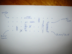
I've never done any electronics before but this exup circuit looks worth a try. I did a bit of reading on simple circuits and fitting the
components correctly so now I've drawn the components as if I were fitting them onto stripboard. Can anyone tell me if I'm going about this
the right way or have I completely screwed it up?
Also is the BC547 transistor OK as I can't find a BC847 on Maplins.
Cheers Steve.
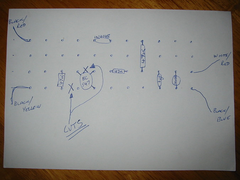 
Rescued attachment IMG_1428.JPG
|
|
|
Bob C
|
| posted on 13/1/06 at 12:24 PM |
|
|
Yo 'highspeeddirt'
good try - the BC547 will be fine.
tip - use a -4mm drill to do the track cuts (just spin it in your fingers)- it makes a hole useless but the hole guides the drill to cut the track
nicely. - heres a pic of something else
http://www.locostbuilders.co.uk/photos.php?action=showphoto&photo=Dsc00532.jpg
put the transistor on to 3 strips in line.
Shame I didn't photograph my prototype from the other side! I'll try to come up with a picture like yours tonight & post it on
here.
cheers
Bob
[Edited on 13/1/06 by Bob C]
|
|
|
highspeeddirt
|
| posted on 13/1/06 at 05:30 PM |
|
|
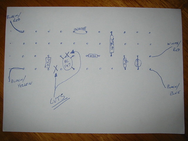
Cheers Bob. I've had another go and this time I've added the anode, cathode and BCE for the transistor. Is this any nearer?
Steve
 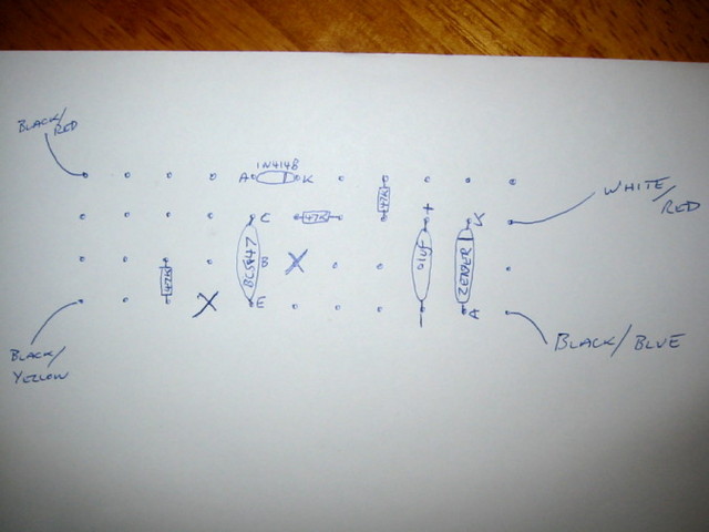
Rescued attachment IMG_1429.JPG
|
|
|
Bob C
|
| posted on 13/1/06 at 06:08 PM |
|
|
Only 1 fault I can see - the resistor in the transistor collector is shorted to itself. Loop the resistor leg over the other side of the collector
& you'll have room to make the cut.
cheers
Bob
|
|
|
highspeeddirt
|
| posted on 13/1/06 at 06:48 PM |
|
|
Like this?
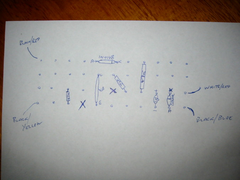 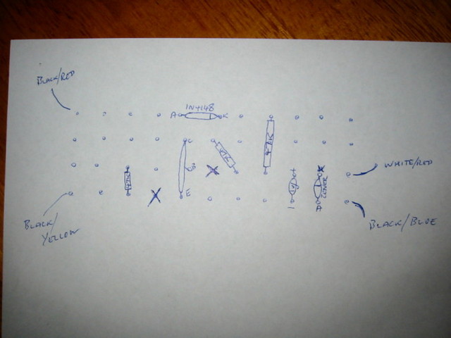
Rescued attachment IMG_1430.JPG
|
|
|
highspeeddirt
|
| posted on 13/1/06 at 06:52 PM |
|
|
I guess I also need to put the IN4148 two holes apart and cut under it as well.
Steve
|
|
|
Bob C
|
| posted on 13/1/06 at 07:01 PM |
|
|
Hah - good point.!
Good luck with it!
Bob
|
|
|
highspeeddirt
|
| posted on 13/1/06 at 09:08 PM |
|
|
I've just noticed the wiring on my 03 exup differs from the earlier models. There is no black/yellow. Instead there are two black/blues. I
assume from Jim Giblett's post that it works on an 03 motor so what has to connect where?
Also a final question, where does the positive leg on the capacitor connect? I think it's the bottom row but want to be sure.
Thanks Steve.
[Edited on 13/1/06 by highspeeddirt]
|
|
|
Bob C
|
| posted on 14/1/06 at 12:07 PM |
|
|
+ side of polarised caps (and LEDs) is always the longer lead. The neg side connects to the transistor emitter.
as to the wiring - the exup has connections to both plugs on the ignition module (carbed models) one has exup motor connections (bla/red and bla/yel)
and the other has the feedback pot connections (bla/blu and whi/red)
Hope that helps you work it out!
cheers
Bob
PS - what I call bla/yel; jim called it bla/green so there may be a colour change.... I suspect one of your bla/blu is what jim called bla/green.
[Edited on 14/1/06 by Bob C]
|
|
|
highspeeddirt
|
| posted on 14/1/06 at 04:40 PM |
|
|
Thanks again Bob.
You're right one of my black/blues is in fact black/green. So that makes more sense. The components arrived this morning so now I'll see
how good my soldering is!
Cheers Steve
|
|
|